Tikz - Mechanical Systems
Table of Contents
1 Mass-Spring Systems
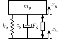
1.1 One mass
\def\massw{2.2}   % Width of the masses
\def\massh{0.8}   % Height of the masses
\def\spaceh{1.4}  % Height of the springs/dampers
\def\dispw{0.3}   % Width of the dashed line for the displacement
\def\disph{0.5}   % Height of the arrow for the displacements
\def\bracs{0.05}  % Brace spacing vertically
\def\brach{-10pt} % Brace shift horizontaly
\draw (-0.5*\massw, 0) -- (0.5*\massw, 0);
\draw[dashed] (0.5*\massw, 0) -- ++(\dispw, 0);
\draw[->] (0.5*\massw+0.5*\dispw, 0) -- ++(0, \disph) node[right]{$x_{w}$};
% Mass
\draw[fill=white] (-0.5*\massw, \spaceh) rectangle (0.5*\massw, \spaceh+\massh) node[pos=0.5]{$m_{g}$};

% Spring, Damper, and Actuator
\draw[spring] (-0.4*\massw, 0) -- (-0.4*\massw, \spaceh) node[midway, left=0.1]{$k_{g}$};
\draw[damper] (0, 0)           -- ( 0, \spaceh)          node[midway, left=0.2]{$c_{g}$};
\draw[actuator] ( 0.4*\massw, 0) -- ( 0.4*\massw, \spaceh) node[midway, left=0.1](F){$F_{g}$};

% Displacements
\draw[dashed] (0.5*\massw, \spaceh) -- ++(\dispw, 0);
\draw[->] (0.5*\massw+0.5*\dispw, \spaceh) -- ++(0, \disph) node[right]{$x_{g}$};

% Legend
% \draw[decorate, decoration={brace, amplitude=8pt}, xshift=\brach] %
%   (-0.5*\massw, \bracs) -- (-0.5*\massw, \spaceh+\massh-\bracs) %
%   node[midway,rotate=90,anchor=south,yshift=10pt]{};
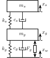
1.2 Two masses
\begin{tikzpicture}
  % ====================
  % Parameters
  % ====================
  \def\massw{2.2}  % Width of the masses
  \def\massh{0.8}  % Height of the masses
  \def\spaceh{1.2} % Height of the springs/dampers
  \def\dispw{0.3}  % Width of the dashed line for the displacement
  \def\disph{0.5}  % Height of the arrow for the displacements
  \def\bracs{0.05} % Brace spacing vertically
  \def\brach{-10pt} % Brace shift horizontaly
  % ====================


  % ====================
  % Ground
  % ====================
  \draw (-0.5*\massw, 0) -- (0.5*\massw, 0);
  \draw[dashed] (0.5*\massw, 0) -- ++(\dispw, 0);
  \draw[->] (0.5*\massw+0.5*\dispw, 0) -- ++(0, \disph) node[right]{$x_{w}$};
  % ====================

  \begin{scope}[shift={(0, 0)}]
    % Mass
    \draw[fill=white] (-0.5*\massw, \spaceh) rectangle (0.5*\massw, \spaceh+\massh) node[pos=0.5]{$m_{g}$};

    % Spring, Damper, and Actuator
    \draw[spring] (-0.4*\massw, 0) -- (-0.4*\massw, \spaceh) node[midway, left=0.1]{$k_{g}$};
    \draw[damper] (0, 0)           -- ( 0, \spaceh)          node[midway, left=0.2]{$c_{g}$};
    \draw[actuator] ( 0.4*\massw, 0) -- ( 0.4*\massw, \spaceh) node[midway, left=0.1](F){$F_{g}$};

    % Displacements
    \draw[dashed] (0.5*\massw, \spaceh) -- ++(\dispw, 0);
    \draw[->] (0.5*\massw+0.5*\dispw, \spaceh) -- ++(0, \disph) node[right]{$x_{g}$};

    % Legend
    % \draw[decorate, decoration={brace, amplitude=8pt}, xshift=\brach] %
    %   (-0.5*\massw, \bracs) -- (-0.5*\massw, \spaceh+\massh-\bracs) %
    %   node[midway,rotate=90,anchor=south,yshift=10pt]{};
  \end{scope}

  \begin{scope}[shift={(0, \spaceh+\massh)}]
    % Mass
    \draw[fill=white] (-0.5*\massw, \spaceh) rectangle (0.5*\massw, \spaceh+\massh) node[pos=0.5]{$m_{s}$};

    % Spring, Damper, and Actuator
    \draw[spring] (-0.4*\massw, 0) -- (-0.4*\massw, \spaceh) node[midway, left=0.1]{$k_{s}$};
    \draw[damper] (0, 0)           -- ( 0, \spaceh)          node[midway, left=0.2]{$c_{s}$};

    % Displacements
    \draw[dashed] (0.5*\massw, \spaceh) -- ++(\dispw, 0);
    \draw[->] (0.5*\massw+0.5*\dispw, \spaceh) -- ++(0, \disph) node[right]{$x_{s}$};

    % Legend
    % \draw[decorate, decoration={brace, amplitude=8pt}, xshift=\brach] %
    %   (-0.5*\massw, \bracs) -- (-0.5*\massw, \spaceh+\massh-\bracs) %
    %   node[midway,rotate=90,anchor=south,yshift=10pt]{};
  \end{scope}
\end{tikzpicture}
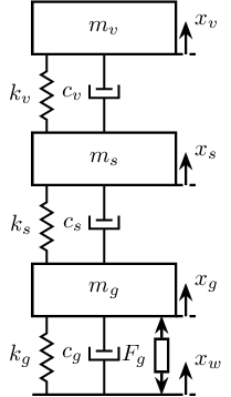
1.3 Three masses
\begin{tikzpicture}
  % ====================
  % Parameters
  % ====================
  \def\massw{2.2}  % Width of the masses
  \def\massh{0.8}  % Height of the masses
  \def\spaceh{1.2} % Height of the springs/dampers
  \def\dispw{0.3}  % Width of the dashed line for the displacement
  \def\disph{0.5}  % Height of the arrow for the displacements
  \def\bracs{0.05} % Brace spacing vertically
  \def\brach{-10pt} % Brace shift horizontaly
  % ====================


  % ====================
  % Ground
  % ====================
  \draw (-0.5*\massw, 0) -- (0.5*\massw, 0);
  \draw[dashed] (0.5*\massw, 0) -- ++(\dispw, 0);
  \draw[->] (0.5*\massw+0.5*\dispw, 0) -- ++(0, \disph) node[right]{$x_{w}$};
  % ====================

  % Granite
  \begin{scope}[shift={(0, 0)}]
    % Mass
    \draw[fill=white] (-0.5*\massw, \spaceh) rectangle (0.5*\massw, \spaceh+\massh) node[pos=0.5]{$m_{g}$};

    % Spring, Damper, and Actuator
    \draw[spring] (-0.4*\massw, 0) -- (-0.4*\massw, \spaceh) node[midway, left=0.1]{$k_{g}$};
    \draw[damper] (0, 0)           -- ( 0, \spaceh)          node[midway, left=0.2]{$c_{g}$};
    \draw[actuator] ( 0.4*\massw, 0) -- ( 0.4*\massw, \spaceh) node[midway, left=0.1](F){$F_{g}$};

    % Displacements
    \draw[dashed] (0.5*\massw, \spaceh) -- ++(\dispw, 0);
    \draw[->] (0.5*\massw+0.5*\dispw, \spaceh) -- ++(0, \disph) node[right]{$x_{g}$};

    % Legend
    % \draw[decorate, decoration={brace, amplitude=8pt}, xshift=\brach] %
    %   (-0.5*\massw, \bracs) -- (-0.5*\massw, \spaceh+\massh-\bracs) %
    %   node[midway,rotate=90,anchor=south,yshift=10pt]{Support};
  \end{scope}

  % Stages
  \begin{scope}[shift={(0, \spaceh+\massh)}]
    % Mass
    \draw[fill=white] (-0.5*\massw, \spaceh) rectangle (0.5*\massw, \spaceh+\massh) node[pos=0.5]{$m_{s}$};

    % Spring, Damper, and Actuator
    \draw[spring] (-0.4*\massw, 0) -- (-0.4*\massw, \spaceh) node[midway, left=0.1]{$k_{s}$};
    \draw[damper] (0, 0)           -- ( 0, \spaceh)          node[midway, left=0.2]{$c_{s}$};

    % Displacements
    \draw[dashed] (0.5*\massw, \spaceh) -- ++(\dispw, 0);
    \draw[->] (0.5*\massw+0.5*\dispw, \spaceh) -- ++(0, \disph) node[right]{$x_{s}$};

    % Legend
    % \draw[decorate, decoration={brace, amplitude=8pt}, xshift=\brach] %
    %   (-0.5*\massw, \bracs) -- (-0.5*\massw, \spaceh+\massh-\bracs) %
    %   node[midway,rotate=90,anchor=south,yshift=10pt]{Actuator};
  \end{scope}

  % Hexapod
  \begin{scope}[shift={(0, 2*(\spaceh+\massh))}]
    % Mass
    \draw[fill=white] (-0.5*\massw, \spaceh) rectangle (0.5*\massw, \spaceh+\massh) node[pos=0.5]{$m_{v}$};

    % Spring, Damper, and Actuator
    \draw[spring] (-0.4*\massw, 0) -- (-0.4*\massw, \spaceh) node[midway, left=0.1]{$k_{v}$};
    \draw[damper] (0, 0)           -- ( 0, \spaceh)          node[midway, left=0.2]{$c_{v}$};

    % Displacements
    \draw[dashed] (0.5*\massw, \spaceh) -- ++(\dispw, 0);
    \draw[->] (0.5*\massw+0.5*\dispw, \spaceh) -- ++(0, \disph) node[right]{$x_{v}$};

    % Legend
    % \draw[decorate, decoration={brace, amplitude=8pt}, xshift=\brach] %
    %   (-0.5*\massw, \bracs) -- (-0.5*\massw, \spaceh+\massh-\bracs) %
    %   node[midway,rotate=90,anchor=south,yshift=10pt]{Flexibility};
  \end{scope}
\end{tikzpicture}
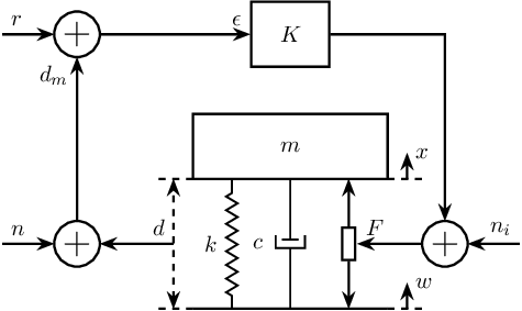
2 Control Based on distance measurement
\begin{tikzpicture}
  % Parameters
  \def\massw{3}
  \def\massh{1}
  \def\spaceh{2}

  % Ground
  \draw[] (-0.5*\massw, 0) -- (0.5*\massw, 0);
  % Mass
  \draw[] (-0.5*\massw, \spaceh) rectangle (0.5*\massw, \spaceh+\massh) node[pos=0.5](m){$m$};

  % Spring, Damper, and Actuator
  \draw[spring]   (-0.3*\massw, 0) -- (-0.3*\massw, \spaceh) node[midway, left=0.1]{$k$};
  \draw[damper]   ( 0, 0) -- ( 0, \spaceh) node[midway, left=0.3]{$c$};
  \draw[actuator] ( 0.3*\massw, 0) -- ( 0.3*\massw, \spaceh) node[midway](F){};

  % Displacements
  \draw[dashed] (0.5*\massw, 0) -- ++(0.2*\massw, 0);
  \draw[->] (0.6*\massw, 0) -- ++(0, 0.2*\spaceh) node[right]{$w$};
  \draw[dashed] (0.5*\massw, \spaceh) -- ++(0.2*\massw, 0);
  \draw[->] (0.6*\massw, \spaceh) -- ++(0, 0.2*\spaceh) node[right]{$x$};

  % Measurement
  \draw[dashed] (-0.5*\massw, 0) -- ++(-0.2*\massw, 0);
  \draw[dashed] (-0.5*\massw, \spaceh) -- ++(-0.2*\massw, 0);
  \draw[dashed, <->] (-0.6*\massw, 0) -- ++(0, \spaceh) node[midway](meas){};

  % Noise
  \node[addb, left=1 of meas] (addn) {};
  \draw[->] (meas.center) node[above left]{$d$} -- (addn.east);
  \draw[<-] (addn.west) -- ++(-0.8, 0) node[above right]{$n$};

  % Controller
  \node[block, above=1 of m] (K) {$K$};

  % Reference signal
  \node[addb] (addr) at (addn|-K){};
  \draw[<-] (addr.west) -- ++(-0.8, 0) node[above right]{$r$};
  \draw[->] (addn.north) -- (addr.south) node[below left]{$d_m$};
  \draw[->] (addr.east) -- (K.west) node[above left]{$\epsilon$};

  % Force injected and input noise
  \node[addb, right=1 of F] (addF) {};
  \draw[->] (K.east) -| (addF.north);
  \draw[->] (addF.west) -- (F.east) node[above right]{$F$};
  \draw[<-] (addF.east) -- ++(0.8, 0) node[above left]{$n_i$};
\end{tikzpicture}
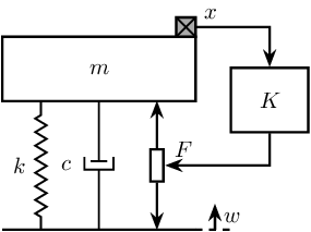
3 Inertial Control
\begin{tikzpicture}
  % Parameters
  \def\massw{3}
  \def\massh{1}
  \def\spaceh{2}

  % Ground
  \draw[] (-0.5*\massw, 0) -- (0.5*\massw, 0);
  % Mass
  \draw[] (-0.5*\massw, \spaceh) rectangle (0.5*\massw, \spaceh+\massh) node[pos=0.5](m){$m$};

  % Spring, Damper, and Actuator
  \draw[spring]   (-0.3*\massw, 0) -- (-0.3*\massw, \spaceh) node[midway, left=0.1]{$k$};
  \draw[damper]   ( 0, 0) -- ( 0, \spaceh) node[midway, left=0.3]{$c$};
  \draw[actuator] ( 0.3*\massw, 0) -- ( 0.3*\massw, \spaceh) node[midway](F){};

  % Displacements
  \draw[dashed] (0.5*\massw, 0) -- ++(0.2*\massw, 0);
  \draw[->] (0.6*\massw, 0) -- ++(0, 0.2*\spaceh) node[below right]{$w$};

  % Inertial Sensor
  \node[inertialsensor] (inertials) at (0.5*\massw, \spaceh+\massh){};

  \node[block, above right=0.5*\massh and 1 of F.east] (K){$K$};

  \draw[->] (inertials.east) node[above right]{$x$} -| (K.north);
  \draw[->] (K.south) |- (F.east) node[above right]{$F$};
\end{tikzpicture}
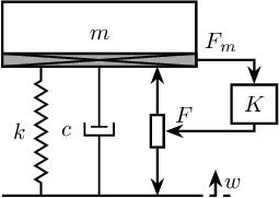
4 Force Feedback Control
\begin{tikzpicture}
  % Parameters
  \def\massw{3}
  \def\massh{1}
  \def\spaceh{2}

  % Ground
  \draw[] (-0.5*\massw, 0) -- (0.5*\massw, 0);
  % Mass
  \draw[] (-0.5*\massw, \spaceh) rectangle (0.5*\massw, \spaceh+\massh) node[pos=0.5](m){$m$};

  % Spring, Damper, and Actuator
  \draw[spring]   (-0.3*\massw, 0) -- (-0.3*\massw, \spaceh) node[midway, left=0.1]{$k$};
  \draw[damper]   ( 0, 0) -- ( 0, \spaceh) node[midway, left=0.3]{$c$};
  \draw[actuator] ( 0.3*\massw, 0) -- ( 0.3*\massw, \spaceh) node[midway](F){};

  % Force Sensor
  \node[forcesensor={\massw}{0.2}] (fsens) at (0, \spaceh){};

  % Displacements
  \draw[dashed] (0.5*\massw, 0) -- ++(0.2*\massw, 0);
  \draw[->] (0.6*\massw, 0) -- ++(0, 0.2*\spaceh) node[below right]{$w$};

  \node[block={0.7cm}{0.6cm}, above right=0.1*\massh and 1 of F.east] (K){$K$};

  \draw[->] (fsens.east) node[above right]{$F_m$} -| (K.north);
  \draw[->] (K.south) |- (F.east) node[above right]{$F$};
\end{tikzpicture}
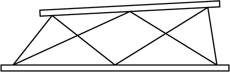
5 Stewart Platform
\begin{tikzpicture}
  \newcommand{\AxisRotator}[1][rotate=0]{%
    \tikz [x=0.25cm,y=0.60cm,line width=.2ex,-stealth,#1] \draw (0,0) arc (-150:150:1 and 1);%
  }

  % Parameters definitions
  \def\baseh{0.2} % Height of the base
  \def\naceh{0.2} % Height of the nacelle
  \def\baser{3.8} % Radius of the base
  \def\nacer{3.0} % Radius of the nacelle

  \def\armr{0.2} % Radius of the arms
  \def\basearmborder{0.2}
  \def\nacearmborder{0.2}

  \def\xnace{0.5} % X position of the nacelle
  \def\ynace{2.0} % Y position of the nacelle
  \def\anace{3.0} % Angle of the nacelle

  \def\xbase{0.0} % X position of the base
  \def\ybase{0.0} % Y position of the base
  \def\abase{0.0} % Angle of the base

  % Hexapod1
  \begin{scope}[shift={(\xbase, \ybase)}, rotate=\abase]
    % Base
    \draw[] (-\baser, 0) rectangle (\baser, \baseh);

    \coordinate[] (armbasel) at (-\baser+\basearmborder+\armr, \baseh);
    \coordinate[] (armbasec) at (0, \baseh);
    \coordinate[] (armbaser) at (\baser-\basearmborder-\armr, \baseh);

    % Nacelle1
    \begin{scope}[shift={(\xnace, \ynace)}, rotate=\anace]
      \draw[] (-\nacer, 0) rectangle (\nacer, \naceh);
      \coordinate[] (armnacel) at (-\nacer+\nacearmborder+\armr, 0);
      \coordinate[] (armnacec) at (0, 0);
      \coordinate[] (armnacer) at (\nacer-\nacearmborder-\armr, 0);
    \end{scope}
    % Nacelle1 END

    \draw[] (armbasec) -- (armnacer);
    \draw[] (armbasec) -- (armnacel);
    \draw[] (armbasel) -- (armnacel);
    \draw[] (armbasel) -- (armnacec);
    \draw[] (armbaser) -- (armnacec);
    \draw[] (armbaser) -- (armnacer);
  \end{scope}
\end{tikzpicture}