Identification of the Stewart Platform using Simscape
Table of Contents
In this document, we discuss the various methods to identify the behavior of the Stewart platform.
1 Modal Analysis of the Stewart Platform
1.1 Initialize the Stewart Platform
stewart = initializeStewartPlatform();
stewart = initializeFramesPositions(stewart);
stewart = generateGeneralConfiguration(stewart);
stewart = computeJointsPose(stewart);
stewart = initializeStrutDynamics(stewart);
stewart = initializeJointDynamics(stewart, 'type_F', 'universal_p', 'type_M', 'spherical_p');
stewart = initializeCylindricalPlatforms(stewart);
stewart = initializeCylindricalStruts(stewart);
stewart = computeJacobian(stewart);
stewart = initializeStewartPose(stewart);
stewart = initializeInertialSensor(stewart);
ground = initializeGround('type', 'none');
payload = initializePayload('type', 'none');
controller = initializeController('type', 'open-loop');
1.2 Identification
%% Options for Linearized
options = linearizeOptions;
options.SampleTime = 0;

%% Name of the Simulink File
mdl = 'stewart_platform_model';

%% Input/Output definition
clear io; io_i = 1;
io(io_i) = linio([mdl, '/Controller'],              1, 'openinput');  io_i = io_i + 1; % Actuator Force Inputs [N]
io(io_i) = linio([mdl, '/Relative Motion Sensor'],  1, 'openoutput'); io_i = io_i + 1; % Position/Orientation of {B} w.r.t. {A}
io(io_i) = linio([mdl, '/Relative Motion Sensor'],  2, 'openoutput'); io_i = io_i + 1; % Velocity of {B} w.r.t. {A}

%% Run the linearization
G = linearize(mdl, io);
% G.InputName  = {'tau1', 'tau2', 'tau3', 'tau4', 'tau5', 'tau6'};
% G.OutputName = {'Xdx', 'Xdy', 'Xdz', 'Xrx', 'Xry', 'Xrz', 'Vdx', 'Vdy', 'Vdz', 'Vrx', 'Vry', 'Vrz'};
Let’s check the size of G:
size(G)
size(G)
State-space model with 12 outputs, 6 inputs, and 18 states.
'org_babel_eoe'
ans =
    'org_babel_eoe'
We expect to have only 12 states (corresponding to the 6dof of the mobile platform).
Gm = minreal(G);
Gm = minreal(G);
6 states removed.
And indeed, we obtain 12 states.
1.3 Coordinate transformation
We can perform the following transformation using the ss2ss command.
Gt = ss2ss(Gm, Gm.C);
Then, the C matrix of Gt is the unity matrix which means that the states of the state space model are equal to the measurements \(\bm{Y}\).
The measurements are the 6 displacement and 6 velocities of mobile platform with respect to \(\{B\}\).
We could perform the transformation by hand:
At = Gm.C*Gm.A*pinv(Gm.C);

Bt = Gm.C*Gm.B;

Ct = eye(12);
Dt = zeros(12, 6);

Gt = ss(At, Bt, Ct, Dt);
1.4 Analysis
[V,D] = eig(Gt.A);
| Mode Number | Resonance Frequency [Hz] | Damping Ratio [%] |
|---|---|---|
| 1.0 | 780.6 | 0.4 |
| 2.0 | 780.6 | 0.3 |
| 3.0 | 903.9 | 0.3 |
| 4.0 | 1061.4 | 0.3 |
| 5.0 | 1061.4 | 0.2 |
| 6.0 | 1269.6 | 0.2 |
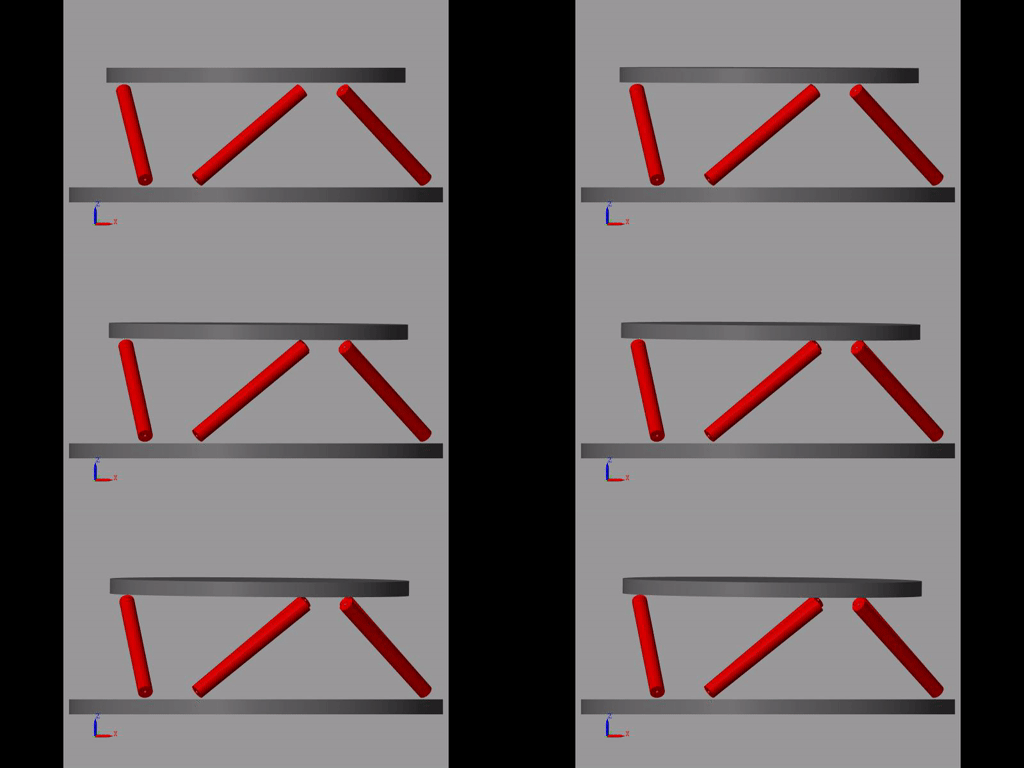
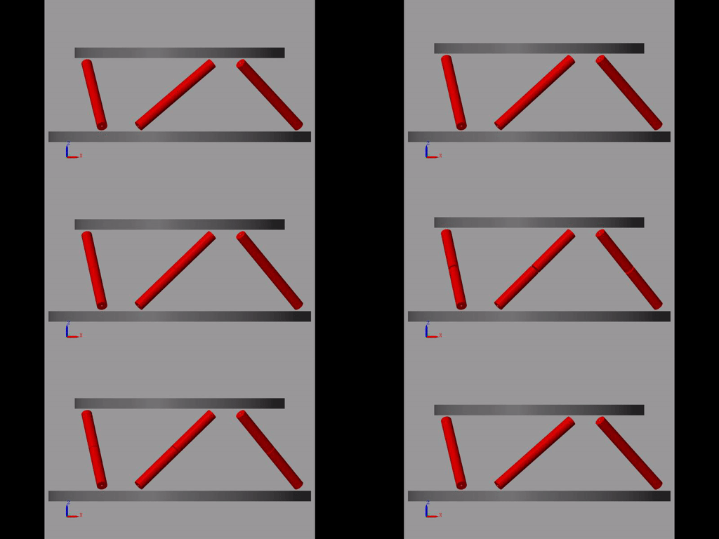
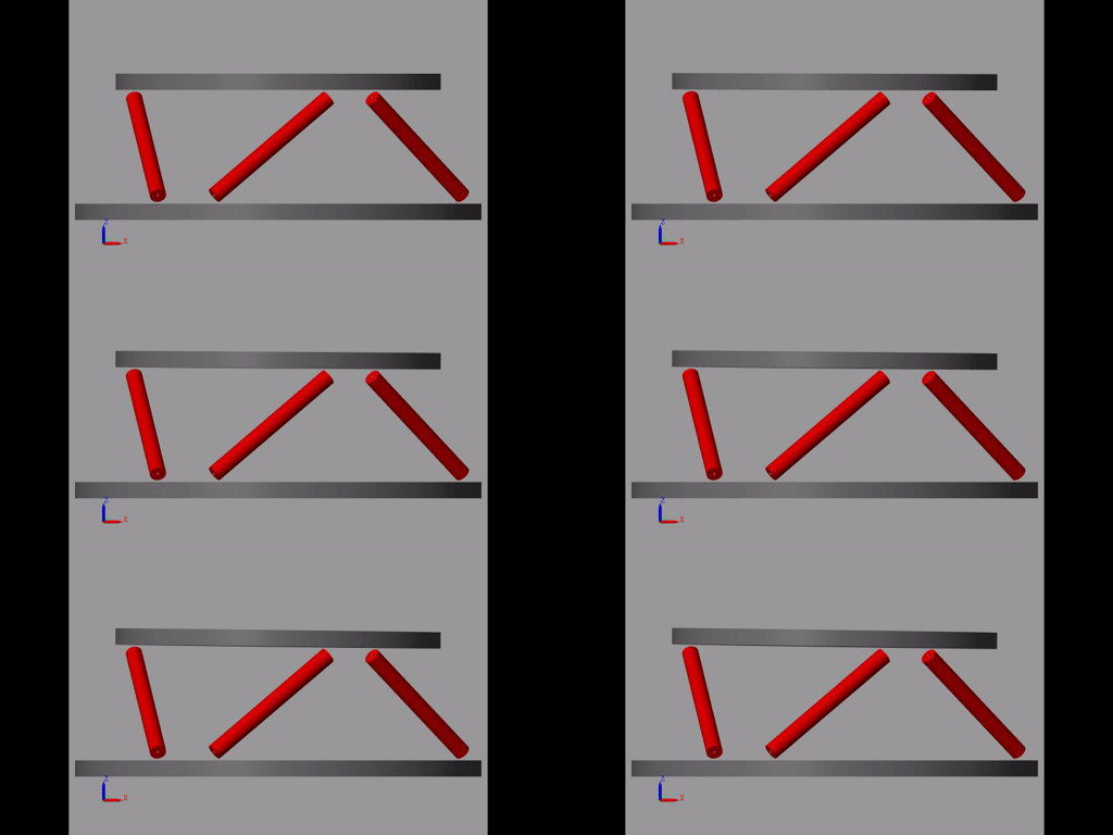
1.5 Visualizing the modes
To visualize the i’th mode, we may excite the system using the inputs \(U_i\) such that \(B U_i\) is co-linear to \(\xi_i\) (the mode we want to excite).
\[ U(t) = e^{\alpha t} ( ) \]
Let’s first sort the modes and just take the modes corresponding to a eigenvalue with a positive imaginary part.
ws = imag(diag(D));
[ws,I] = sort(ws)
ws = ws(7:end); I = I(7:end);
for i = 1:length(ws)
i_mode = I(i); % the argument is the i'th mode
lambda_i = D(i_mode, i_mode);
xi_i = V(:,i_mode);

a_i = real(lambda_i);
b_i = imag(lambda_i);
Let do 10 periods of the mode.
t = linspace(0, 10/(imag(lambda_i)/2/pi), 1000);
U_i = pinv(Gt.B) * real(xi_i * lambda_i * (cos(b_i * t) + 1i*sin(b_i * t)));
U = timeseries(U_i, t);
Simulation:
load('mat/conf_simscape.mat');
set_param(conf_simscape, 'StopTime', num2str(t(end)));
sim(mdl);
Save the movie of the mode shape.
smwritevideo(mdl, sprintf('figs/mode%i', i), ...
             'PlaybackSpeedRatio', 1/(b_i/2/pi), ...
             'FrameRate', 30, ...
             'FrameSize', [800, 400]);
end

Figure 1: Identified mode - 1

Figure 2: Identified mode - 3

Figure 3: Identified mode - 5
2 Transmissibility Analysis
2.1 Initialize the Stewart platform
stewart = initializeStewartPlatform();
stewart = initializeFramesPositions(stewart, 'H', 90e-3, 'MO_B', 45e-3);
stewart = generateGeneralConfiguration(stewart);
stewart = computeJointsPose(stewart);
stewart = initializeStrutDynamics(stewart);
stewart = initializeJointDynamics(stewart, 'type_F', 'universal_p', 'type_M', 'spherical_p');
stewart = initializeCylindricalPlatforms(stewart);
stewart = initializeCylindricalStruts(stewart);
stewart = computeJacobian(stewart);
stewart = initializeStewartPose(stewart);
stewart = initializeInertialSensor(stewart, 'type', 'accelerometer', 'freq', 5e3);
We set the rotation point of the ground to be at the same point at frames \(\{A\}\) and \(\{B\}\).
ground = initializeGround('type', 'rigid', 'rot_point', stewart.platform_F.FO_A);
payload = initializePayload('type', 'rigid');
controller = initializeController('type', 'open-loop');
2.2 Transmissibility
%% Options for Linearized
options = linearizeOptions;
options.SampleTime = 0;

%% Name of the Simulink File
mdl = 'stewart_platform_model';

%% Input/Output definition
clear io; io_i = 1;
io(io_i) = linio([mdl, '/Disturbances/D_w'],        1, 'openinput');  io_i = io_i + 1; % Base Motion [m, rad]
io(io_i) = linio([mdl, '/Absolute Motion Sensor'],  1, 'openoutput'); io_i = io_i + 1; % Absolute Motion [m, rad]

%% Run the linearization
T = linearize(mdl, io, options);
T.InputName = {'Wdx', 'Wdy', 'Wdz', 'Wrx', 'Wry', 'Wrz'};
T.OutputName = {'Edx', 'Edy', 'Edz', 'Erx', 'Ery', 'Erz'};
freqs = logspace(1, 4, 1000);

figure;
for ix = 1:6
  for iy = 1:6
    subplot(6, 6, (ix-1)*6 + iy);
    hold on;
    plot(freqs, abs(squeeze(freqresp(T(ix, iy), freqs, 'Hz'))), 'k-');
    set(gca, 'XScale', 'log'); set(gca, 'YScale', 'log');
    ylim([1e-5, 10]);
    xlim([freqs(1), freqs(end)]);
    if ix < 6
      xticklabels({});
    end
    if iy > 1
      yticklabels({});
    end
  end
end
From (Preumont et al. 2007), one can use the Frobenius norm of the transmissibility matrix to obtain a scalar indicator of the transmissibility performance of the system:
\begin{align*} \| \bm{T}(\omega) \| &= \sqrt{\text{Trace}[\bm{T}(\omega) \bm{T}(\omega)^H]}\\ &= \sqrt{\Sigma_{i=1}^6 \Sigma_{j=1}^6 |T_{ij}|^2} \end{align*}freqs = logspace(1, 4, 1000); T_norm = zeros(length(freqs), 1); for i = 1:length(freqs) T_norm(i) = sqrt(trace(freqresp(T, freqs(i), 'Hz')*freqresp(T, freqs(i), 'Hz')')); end
And we normalize by a factor \(\sqrt{6}\) to obtain a performance metric comparable to the transmissibility of a one-axis isolator: \[ \Gamma(\omega) = \|\bm{T}(\omega)\| / \sqrt{6} \]
Gamma = T_norm/sqrt(6);
figure;
plot(freqs, Gamma)
set(gca, 'XScale', 'log'); set(gca, 'YScale', 'log');
3 Compliance Analysis
3.1 Initialize the Stewart platform
stewart = initializeStewartPlatform();
stewart = initializeFramesPositions(stewart, 'H', 90e-3, 'MO_B', 45e-3);
stewart = generateGeneralConfiguration(stewart);
stewart = computeJointsPose(stewart);
stewart = initializeStrutDynamics(stewart);
stewart = initializeJointDynamics(stewart, 'type_F', 'universal_p', 'type_M', 'spherical_p');
stewart = initializeCylindricalPlatforms(stewart);
stewart = initializeCylindricalStruts(stewart);
stewart = computeJacobian(stewart);
stewart = initializeStewartPose(stewart);
stewart = initializeInertialSensor(stewart, 'type', 'accelerometer', 'freq', 5e3);
We set the rotation point of the ground to be at the same point at frames \(\{A\}\) and \(\{B\}\).
ground = initializeGround('type', 'none');
payload = initializePayload('type', 'rigid');
controller = initializeController('type', 'open-loop');
3.2 Compliance
%% Options for Linearized
options = linearizeOptions;
options.SampleTime = 0;

%% Name of the Simulink File
mdl = 'stewart_platform_model';

%% Input/Output definition
clear io; io_i = 1;
io(io_i) = linio([mdl, '/Disturbances/F_ext'],        1, 'openinput');  io_i = io_i + 1; % Base Motion [m, rad]
io(io_i) = linio([mdl, '/Absolute Motion Sensor'],  1, 'openoutput'); io_i = io_i + 1; % Absolute Motion [m, rad]

%% Run the linearization
C = linearize(mdl, io, options);
C.InputName = {'Fdx', 'Fdy', 'Fdz', 'Mdx', 'Mdy', 'Mdz'};
C.OutputName = {'Edx', 'Edy', 'Edz', 'Erx', 'Ery', 'Erz'};
freqs = logspace(1, 4, 1000);

figure;
for ix = 1:6
  for iy = 1:6
    subplot(6, 6, (ix-1)*6 + iy);
    hold on;
    plot(freqs, abs(squeeze(freqresp(C(ix, iy), freqs, 'Hz'))), 'k-');
    set(gca, 'XScale', 'log'); set(gca, 'YScale', 'log');
    ylim([1e-10, 1e-3]);
    xlim([freqs(1), freqs(end)]);
    if ix < 6
      xticklabels({});
    end
    if iy > 1
      yticklabels({});
    end
  end
end
We can try to use the Frobenius norm to obtain a scalar value representing the 6-dof compliance of the Stewart platform.
freqs = logspace(1, 4, 1000);

C_norm = zeros(length(freqs), 1);

for i = 1:length(freqs)
  C_norm(i) = sqrt(trace(freqresp(C, freqs(i), 'Hz')*freqresp(C, freqs(i), 'Hz')'));
end
figure;
plot(freqs, C_norm)
set(gca, 'XScale', 'log'); set(gca, 'YScale', 'log');
4 Functions
4.1 Compute the Transmissibility
Function description
function [T, T_norm, freqs] = computeTransmissibility(args)
% computeTransmissibility -
%
% Syntax: [T, T_norm, freqs] = computeTransmissibility(args)
%
% Inputs:
%    - args - Structure with the following fields:
%        - plots [true/false] - Should plot the transmissilibty matrix and its Frobenius norm
%        - freqs [] - Frequency vector to estimate the Frobenius norm
%
% Outputs:
%    - T      [6x6 ss] - Transmissibility matrix
%    - T_norm [length(freqs)x1] - Frobenius norm of the Transmissibility matrix
%    - freqs  [length(freqs)x1] - Frequency vector in [Hz]
Optional Parameters
arguments
  args.plots logical {mustBeNumericOrLogical} = false
  args.freqs double {mustBeNumeric, mustBeNonnegative} = logspace(1,4,1000)
end
freqs = args.freqs;
Identification of the Transmissibility Matrix
%% Options for Linearized
options = linearizeOptions;
options.SampleTime = 0;

%% Name of the Simulink File
mdl = 'stewart_platform_model';

%% Input/Output definition
clear io; io_i = 1;
io(io_i) = linio([mdl, '/Disturbances/D_w'],        1, 'openinput');  io_i = io_i + 1; % Base Motion [m, rad]
io(io_i) = linio([mdl, '/Absolute Motion Sensor'],  1, 'output'); io_i = io_i + 1; % Absolute Motion [m, rad]

%% Run the linearization
T = linearize(mdl, io, options);
T.InputName = {'Wdx', 'Wdy', 'Wdz', 'Wrx', 'Wry', 'Wrz'};
T.OutputName = {'Edx', 'Edy', 'Edz', 'Erx', 'Ery', 'Erz'};
If wanted, the 6x6 transmissibility matrix is plotted.
p_handle = zeros(6*6,1);

if args.plots
  fig = figure;
  for ix = 1:6
    for iy = 1:6
      p_handle((ix-1)*6 + iy) = subplot(6, 6, (ix-1)*6 + iy);
      hold on;
      plot(freqs, abs(squeeze(freqresp(T(ix, iy), freqs, 'Hz'))), 'k-');
      set(gca, 'XScale', 'log'); set(gca, 'YScale', 'log');
      if ix < 6
          xticklabels({});
      end
      if iy > 1
          yticklabels({});
      end
    end
  end

  linkaxes(p_handle, 'xy')
  xlim([freqs(1), freqs(end)]);
  ylim([1e-5, 1e2]);

  han = axes(fig, 'visible', 'off');
  han.XLabel.Visible = 'on';
  han.YLabel.Visible = 'on';
  xlabel(han, 'Frequency [Hz]');
  ylabel(han, 'Transmissibility [m/m]');
end
Computation of the Frobenius norm
T_norm = zeros(length(freqs), 1);

for i = 1:length(freqs)
  T_norm(i) = sqrt(trace(freqresp(T, freqs(i), 'Hz')*freqresp(T, freqs(i), 'Hz')'));
end
T_norm = T_norm/sqrt(6);
if args.plots
  figure;
  plot(freqs, T_norm)
  set(gca, 'XScale', 'log'); set(gca, 'YScale', 'log');
  xlabel('Frequency [Hz]');
  ylabel('Transmissibility - Frobenius Norm');
end
4.2 Compute the Compliance
Function description
function [C, C_norm, freqs] = computeCompliance(args)
% computeCompliance -
%
% Syntax: [C, C_norm, freqs] = computeCompliance(args)
%
% Inputs:
%    - args - Structure with the following fields:
%        - plots [true/false] - Should plot the transmissilibty matrix and its Frobenius norm
%        - freqs [] - Frequency vector to estimate the Frobenius norm
%
% Outputs:
%    - C      [6x6 ss] - Compliance matrix
%    - C_norm [length(freqs)x1] - Frobenius norm of the Compliance matrix
%    - freqs  [length(freqs)x1] - Frequency vector in [Hz]
Optional Parameters
arguments
  args.plots logical {mustBeNumericOrLogical} = false
  args.freqs double {mustBeNumeric, mustBeNonnegative} = logspace(1,4,1000)
end
freqs = args.freqs;
Identification of the Compliance Matrix
%% Options for Linearized
options = linearizeOptions;
options.SampleTime = 0;

%% Name of the Simulink File
mdl = 'stewart_platform_model';

%% Input/Output definition
clear io; io_i = 1;
io(io_i) = linio([mdl, '/Disturbances/F_ext'],      1, 'openinput');  io_i = io_i + 1; % External forces [N, N*m]
io(io_i) = linio([mdl, '/Absolute Motion Sensor'],  1, 'output'); io_i = io_i + 1; % Absolute Motion [m, rad]

%% Run the linearization
C = linearize(mdl, io, options);
C.InputName  = {'Fdx', 'Fdy', 'Fdz', 'Mdx', 'Mdy', 'Mdz'};
C.OutputName = {'Edx', 'Edy', 'Edz', 'Erx', 'Ery', 'Erz'};
If wanted, the 6x6 transmissibility matrix is plotted.
p_handle = zeros(6*6,1);

if args.plots
  fig = figure;
  for ix = 1:6
    for iy = 1:6
      p_handle((ix-1)*6 + iy) = subplot(6, 6, (ix-1)*6 + iy);
      hold on;
      plot(freqs, abs(squeeze(freqresp(C(ix, iy), freqs, 'Hz'))), 'k-');
      set(gca, 'XScale', 'log'); set(gca, 'YScale', 'log');
      if ix < 6
          xticklabels({});
      end
      if iy > 1
          yticklabels({});
      end
    end
  end

  linkaxes(p_handle, 'xy')
  xlim([freqs(1), freqs(end)]);

  han = axes(fig, 'visible', 'off');
  han.XLabel.Visible = 'on';
  han.YLabel.Visible = 'on';
  xlabel(han, 'Frequency [Hz]');
  ylabel(han, 'Compliance [m/N, rad/(N*m)]');
end
Computation of the Frobenius norm
freqs = args.freqs;

C_norm = zeros(length(freqs), 1);

for i = 1:length(freqs)
  C_norm(i) = sqrt(trace(freqresp(C, freqs(i), 'Hz')*freqresp(C, freqs(i), 'Hz')'));
end
if args.plots
  figure;
  plot(freqs, C_norm)
  set(gca, 'XScale', 'log'); set(gca, 'YScale', 'log');
  xlabel('Frequency [Hz]');
  ylabel('Compliance - Frobenius Norm');
end