Tikz - Optics
Table of Contents
1 Optics
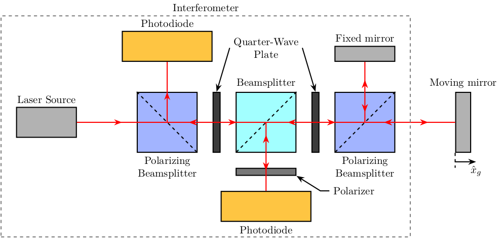
1.1 Interferometer - Schematic
\begin{tikzpicture}
  % Parameters definitions
  \def\splitw{2.0cm} % Width of the split mirrors
  \def\splith{2.0cm} % Height of the split mirrors

  \def\photow{3.0cm} % Width of the photodiodes
  \def\photoh{1.0cm} % Height of the photodiodes

  \def\mirrorw{1.0cm} % Width of the mirrors
  \def\mirrorh{1.5cm} % Height of the mirrors

  \def\spacing{1.0cm} % First intersection of the beam

  % Colors
  \definecolor{c_beamsplitter}{RGB}{162,255,255} % light blue
  \definecolor{c_photodiode}{RGB}{254,197,66} % light orange
  \definecolor{c_mirror}{RGB}{178,178,178} % light grey
  \definecolor{c_polar_beamsplitter}{RGB}{162, 180, 255} % blue
  \definecolor{c_polarizer}{RGB}{120,120,120} % light grey
  \definecolor{c_quart_wave_plate}{RGB}{60,60,60} % light grey


  % Styles
  \tikzstyle{laser}             = [draw, fill=c_mirror, minimum width=2.0cm, minimum height=1.0cm]
  \tikzstyle{beamsplitter}       = [draw, fill=c_beamsplitter, minimum width=2.0cm, minimum height=2.0cm]
  \tikzstyle{polar_beamsplitter} = [draw, fill=c_polar_beamsplitter, minimum width=2.0cm, minimum height=2.0cm]
  \tikzstyle{photodiode}        = [draw, fill=c_photodiode, minimum width=3.0cm, minimum height=1.0cm]
  \tikzstyle{quart_wave_plate}  = [draw, fill=c_quart_wave_plate, minimum width=0.1cm, minimum height=2.0cm]
  \tikzstyle{polarizer}         = [draw, fill=c_polarizer, minimum width=2.0cm, minimum height=0.1cm]
  \tikzstyle{mirror}            = [draw, fill=c_mirror, minimum width=0.5cm, minimum height=2.0cm]
  \tikzstyle{mirror_hor}        = [draw, fill=c_mirror, minimum width=2.0cm, minimum height=0.5cm]


  % Elements
  \node[laser]                                             (laser) {};
  \node[polar_beamsplitter,   right=2.0*\spacing of laser] (PBS1) {};
  \node[photodiode,           above=1.0*\spacing of PBS1]  (PD1) {};
  \node[quart_wave_plate,     right=0.5*\spacing of PBS1]  (WP1) {};
  \node[beamsplitter,         right=0.5*\spacing of WP1]   (BS) {};
  \node[polarizer,            below=0.5*\spacing of BS]    (P) {};
  \node[photodiode,           below=0.5*\spacing of P]     (PD2) {};
  \node[quart_wave_plate,     right=0.5*\spacing of BS]    (WP2) {};
  \node[polar_beamsplitter,   right=0.5*\spacing of WP2]   (PBS2) {};
  \node[mirror,               right=2.0*\spacing of PBS2]  (M2) {};
  \node[mirror_hor,           above=1.0*\spacing of PBS2]  (M1) {};

  % Beam Splitter orientations
  \draw[dashed] (PBS1.north west) -- (PBS1.south east);
  \draw[dashed] (BS.north east) -- (BS.south west);
  \draw[dashed] (PBS2.north east) -- (PBS2.south west);

  % LASER
  \draw[red, ->-=.5]         (laser.east)  -- (PBS1.center);
  \draw[red, ->-=.5]         (PBS1.center) -- (PD1.south);
  \draw[red, ->-=.7, -<-=.3] (PBS1.center) -- (BS.center);
  \draw[red, ->-=.7, -<-=.3] (BS.center)   -- (PBS2.center);
  \draw[red, ->-=.7, -<-=.3] (PBS2.center) -- (M1.south);
  \draw[red, ->-=.7, -<-=.3] (PBS2.center) -- (M2.west);
  \draw[red, ->-=.7, -<-=.3] (BS.center)   -- (PD2.north);

  % Nomenclature
  \path[] (laser.north) node[above]{Laser Source};
  \path[] (PBS1.south)  node[below, align=center]{Polarizing\\ Beamsplitter};
  \path[] (PBS2.south)  node[below, align=center]{Polarizing\\ Beamsplitter};
  \path[] (BS.north)    node[above]{Beamsplitter};
  \path[] (PD1.north)   node[above]{Photodiode};
  \path[] (PD2.south)   node[below]{Photodiode};
  \path[] (M1.north)    node[above]{Fixed mirror};
  \path[] (M2.north)    node[above]{Moving mirror};
  \draw[<-] (P.south east) -- ++(0.8*\spacing, -0.5*\spacing) -- ++(0.3*\spacing, 0) node[right]{Polarizer};
  \node[above=\spacing of BS, align=center] (quarter_BS_label) {Quarter-Wave\\ Plate};
  \draw[<-] (WP2.north) -- (quarter_BS_label.east);
  \draw[<-] (WP1.north) -- (quarter_BS_label.west);

  % Xg
  \draw[dashed] (M2.south west) --++(0, -0.5*\spacing);
  \draw[->] ($(M2.south west) + (0, -0.3*\spacing)$) -- ++(0.7*\spacing, 0) node[below]{$\hat{x}_g$};

  % Interferometer
  \node[fit={($(laser.west|-PD1.north)+(-0.5*\spacing, 0.5*\spacing)$) ($(PD2.south-|PBS2.east)+(0.5*\spacing, -0.5*\spacing)$)}, inner sep=0pt, draw, dashed, color=gray, label={Interferometer}] (P) {};
\end{tikzpicture}
