Tikz - Mechanical Systems
Table of Contents
- 1. Mass-Spring Systems
- 2. Mass-Spring Systems - bis
- 3. Control Based on distance measurement
- 4. Inertial Control
- 5. Force Feedback Control
- 6. Inertial Sensor
- 7. Mechanical Systems
- 8. 3D
- 9. Gravity Compensation System
- 10. 3Dof System
- 11. 3Dof System - bis
- 12. Rotating System
- 13. Guiding Errors
- 14. Vibration analysis procedure
- 15. Pendulum Experiment
1 Mass-Spring Systems
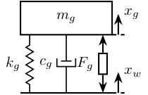
1.1 One mass
\def\massw{2.2}   % Width of the masses
\def\massh{0.8}   % Height of the masses
\def\spaceh{1.4}  % Height of the springs/dampers
\def\dispw{0.3}   % Width of the dashed line for the displacement
\def\disph{0.5}   % Height of the arrow for the displacements
\def\bracs{0.05}  % Brace spacing vertically
\def\brach{-10pt} % Brace shift horizontaly
\draw (-0.5*\massw, 0) -- (0.5*\massw, 0);
\draw[dashed] (0.5*\massw, 0) -- ++(\dispw, 0);
\draw[->] (0.5*\massw+0.5*\dispw, 0) -- ++(0, \disph) node[right]{$x_{w}$};
% Mass
\draw[fill=white] (-0.5*\massw, \spaceh) rectangle (0.5*\massw, \spaceh+\massh) node[pos=0.5]{$m_{g}$};

% Spring, Damper, and Actuator
\draw[spring] (-0.4*\massw, 0) -- (-0.4*\massw, \spaceh) node[midway, left=0.1]{$k_{g}$};
\draw[damper] (0, 0)           -- ( 0, \spaceh)          node[midway, left=0.2]{$c_{g}$};
\draw[actuator] ( 0.4*\massw, 0) -- (   0.4*\massw, \spaceh) node[midway, left=0.1](F){$F_{g}$};

% Displacements
\draw[dashed] (0.5*\massw, \spaceh) -- ++(\dispw, 0);
\draw[->] (0.5*\massw+0.5*\dispw, \spaceh) -- ++(0, \disph) node[right]{$x_{g}$};

% Legend
% \draw[decorate, decoration={brace, amplitude=8pt}, xshift=\brach] %
%   (-0.5*\massw, \bracs) -- (-0.5*\massw, \spaceh+\massh-\bracs) %
%   node[midway,rotate=90,anchor=south,yshift=10pt]{};
\begin{tikzpicture}
  <<tikz_1dof_smd_params>>
  <<tikz_1dof_smd_ground>>
  <<tikz_1dof_smd_mass>>
\end{tikzpicture}
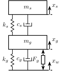
1.2 Two masses
\begin{tikzpicture}
  % ====================
  % Parameters
  % ====================
  \def\massw{2.2}  % Width of the masses
  \def\massh{0.8}  % Height of the masses
  \def\spaceh{1.2} % Height of the springs/dampers
  \def\dispw{0.3}  % Width of the dashed line for the displacement
  \def\disph{0.5}  % Height of the arrow for the displacements
  \def\bracs{0.05} % Brace spacing vertically
  \def\brach{-10pt} % Brace shift horizontaly
  % ====================


  % ====================
  % Ground
  % ====================
  \draw (-0.5*\massw, 0) -- (0.5*\massw, 0);
  \draw[dashed] (0.5*\massw, 0) -- ++(\dispw, 0);
  \draw[->] (0.5*\massw+0.5*\dispw, 0) -- ++(0, \disph) node[right]{$x_{w}$};
  % ====================

  \begin{scope}[shift={(0, 0)}]
    % Mass
    \draw[fill=white] (-0.5*\massw, \spaceh) rectangle (0.5*\massw, \spaceh+\massh) node[pos=0.5]{$m_{g}$};

    % Spring, Damper, and Actuator
    \draw[spring] (-0.4*\massw, 0) -- (-0.4*\massw, \spaceh) node[midway, left=0.1]{$k_{g}$};
    \draw[damper] (0, 0)           -- ( 0, \spaceh)          node[midway, left=0.2]{$c_{g}$};
    \draw[actuator] ( 0.4*\massw, 0) -- (   0.4*\massw, \spaceh) node[midway, left=0.1](F){$F_{g}$};

    % Displacements
    \draw[dashed] (0.5*\massw, \spaceh) -- ++(\dispw, 0);
    \draw[->] (0.5*\massw+0.5*\dispw, \spaceh) -- ++(0, \disph) node[right]{$x_{g}$};

    % Legend
    % \draw[decorate, decoration={brace, amplitude=8pt}, xshift=\brach] %
    %   (-0.5*\massw, \bracs) -- (-0.5*\massw, \spaceh+\massh-\bracs) %
    %   node[midway,rotate=90,anchor=south,yshift=10pt]{};
  \end{scope}

  \begin{scope}[shift={(0, \spaceh+\massh)}]
    % Mass
    \draw[fill=white] (-0.5*\massw, \spaceh) rectangle (0.5*\massw, \spaceh+\massh) node[pos=0.5]{$m_{s}$};

    % Spring, Damper, and Actuator
    \draw[spring] (-0.4*\massw, 0) -- (-0.4*\massw, \spaceh) node[midway, left=0.1]{$k_{s}$};
    \draw[damper] (0, 0)           -- ( 0, \spaceh)          node[midway, left=0.2]{$c_{s}$};

    % Displacements
    \draw[dashed] (0.5*\massw, \spaceh) -- ++(\dispw, 0);
    \draw[->] (0.5*\massw+0.5*\dispw, \spaceh) -- ++(0, \disph) node[right]{$x_{s}$};

    % Legend
    % \draw[decorate, decoration={brace, amplitude=8pt}, xshift=\brach] %
    %   (-0.5*\massw, \bracs) -- (-0.5*\massw, \spaceh+\massh-\bracs) %
    %   node[midway,rotate=90,anchor=south,yshift=10pt]{};
  \end{scope}
\end{tikzpicture}
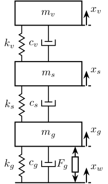
1.3 Three masses
\begin{tikzpicture}
  % ====================
  % Parameters
  % ====================
  \def\massw{2.2}  % Width of the masses
  \def\massh{0.8}  % Height of the masses
  \def\spaceh{1.2} % Height of the springs/dampers
  \def\dispw{0.3}  % Width of the dashed line for the displacement
  \def\disph{0.5}  % Height of the arrow for the displacements
  \def\bracs{0.05} % Brace spacing vertically
  \def\brach{-10pt} % Brace shift horizontaly
  % ====================


  % ====================
  % Ground
  % ====================
  \draw (-0.5*\massw, 0) -- (0.5*\massw, 0);
  \draw[dashed] (0.5*\massw, 0) -- ++(\dispw, 0);
  \draw[->] (0.5*\massw+0.5*\dispw, 0) -- ++(0, \disph) node[right]{$x_{w}$};
  % ====================

  % Granite
  \begin{scope}[shift={(0, 0)}]
    % Mass
    \draw[fill=white] (-0.5*\massw, \spaceh) rectangle (0.5*\massw, \spaceh+\massh) node[pos=0.5]{$m_{g}$};

    % Spring, Damper, and Actuator
    \draw[spring] (-0.4*\massw, 0) -- (-0.4*\massw, \spaceh) node[midway, left=0.1]{$k_{g}$};
    \draw[damper] (0, 0)           -- ( 0, \spaceh)          node[midway, left=0.2]{$c_{g}$};
    \draw[actuator] ( 0.4*\massw, 0) -- (   0.4*\massw, \spaceh) node[midway, left=0.1](F){$F_{g}$};

    % Displacements
    \draw[dashed] (0.5*\massw, \spaceh) -- ++(\dispw, 0);
    \draw[->] (0.5*\massw+0.5*\dispw, \spaceh) -- ++(0, \disph) node[right]{$x_{g}$};

    % Legend
    % \draw[decorate, decoration={brace, amplitude=8pt}, xshift=\brach] %
    %   (-0.5*\massw, \bracs) -- (-0.5*\massw, \spaceh+\massh-\bracs) %
    %   node[midway,rotate=90,anchor=south,yshift=10pt]{Support};
  \end{scope}

  % Stages
  \begin{scope}[shift={(0, \spaceh+\massh)}]
    % Mass
    \draw[fill=white] (-0.5*\massw, \spaceh) rectangle (0.5*\massw, \spaceh+\massh) node[pos=0.5]{$m_{s}$};

    % Spring, Damper, and Actuator
    \draw[spring] (-0.4*\massw, 0) -- (-0.4*\massw, \spaceh) node[midway, left=0.1]{$k_{s}$};
    \draw[damper] (0, 0)           -- ( 0, \spaceh)          node[midway, left=0.2]{$c_{s}$};

    % Displacements
    \draw[dashed] (0.5*\massw, \spaceh) -- ++(\dispw, 0);
    \draw[->] (0.5*\massw+0.5*\dispw, \spaceh) -- ++(0, \disph) node[right]{$x_{s}$};

    % Legend
    % \draw[decorate, decoration={brace, amplitude=8pt}, xshift=\brach] %
    %   (-0.5*\massw, \bracs) -- (-0.5*\massw, \spaceh+\massh-\bracs) %
    %   node[midway,rotate=90,anchor=south,yshift=10pt]{Actuator};
  \end{scope}

  % Hexapod
  \begin{scope}[shift={(0, 2*(\spaceh+\massh))}]
    % Mass
    \draw[fill=white] (-0.5*\massw, \spaceh) rectangle (0.5*\massw, \spaceh+\massh) node[pos=0.5]{$m_{v}$};

    % Spring, Damper, and Actuator
    \draw[spring] (-0.4*\massw, 0) -- (-0.4*\massw, \spaceh) node[midway, left=0.1]{$k_{v}$};
    \draw[damper] (0, 0)           -- ( 0, \spaceh)          node[midway, left=0.2]{$c_{v}$};

    % Displacements
    \draw[dashed] (0.5*\massw, \spaceh) -- ++(\dispw, 0);
    \draw[->] (0.5*\massw+0.5*\dispw, \spaceh) -- ++(0, \disph) node[right]{$x_{v}$};

    % Legend
    % \draw[decorate, decoration={brace, amplitude=8pt}, xshift=\brach] %
    %   (-0.5*\massw, \bracs) -- (-0.5*\massw, \spaceh+\massh-\bracs) %
    %   node[midway,rotate=90,anchor=south,yshift=10pt]{Flexibility};
  \end{scope}
\end{tikzpicture}
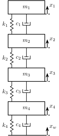
1.4 Four masses
\begin{tikzpicture}
  % ====================
  % Parameters
  \def\massw{2.2}  % Width of the masses
  \def\massh{0.8}  % Height of the masses
  \def\spaceh{1.2} % Height of the springs/dampers
  \def\dispw{0.3}  % Width of the dashed line for the displacement
  \def\disph{0.5}  % Height of the arrow for the displacements
  \def\bracs{0.05} % Brace spacing vertically
  \def\brach{-10pt} % Brace shift horizontaly

  % ====================
  % Ground
  \draw (-0.5*\massw, 0) -- (0.5*\massw, 0);
  \draw[dashed] (0.5*\massw, 0) -- ++(\dispw, 0);
  \draw[->] (0.5*\massw+0.5*\dispw, 0) -- ++(0, \disph) node[right]{$x_{w}$};

  \begin{scope}[shift={(0, 0*(\spaceh+\massh))}]
    % Mass
    \draw[fill=white] (-0.5*\massw, \spaceh) rectangle (0.5*\massw, \spaceh+\massh) node[pos=0.5]{$m_4$};

    % Spring, Damper, and Actuator
    \draw[spring] (-0.4*\massw, 0) -- (-0.4*\massw, \spaceh) node[midway, left=0.1]{$k_4$};
    \draw[damper] (0, 0)           -- ( 0, \spaceh)          node[midway, left=0.2]{$c_4$};

    % Displacements
    \draw[dashed] (0.5*\massw, \spaceh) -- ++(\dispw, 0);
    \draw[->] (0.5*\massw+0.5*\dispw, \spaceh) -- ++(0, \disph) node[right]{$x_4$};
  \end{scope}

  \begin{scope}[shift={(0, 1*(\spaceh+\massh))}]
    % Mass
    \draw[fill=white] (-0.5*\massw, \spaceh) rectangle (0.5*\massw, \spaceh+\massh) node[pos=0.5]{$m_3$};

    % Spring, Damper, and Actuator
    \draw[spring] (-0.4*\massw, 0) -- (-0.4*\massw, \spaceh) node[midway, left=0.1]{$k_3$};
    \draw[damper] (0, 0)           -- ( 0, \spaceh)          node[midway, left=0.2]{$c_3$};

    % Displacements
    \draw[dashed] (0.5*\massw, \spaceh) -- ++(\dispw, 0);
    \draw[->] (0.5*\massw+0.5*\dispw, \spaceh) -- ++(0, \disph) node[right]{$x_3$};
  \end{scope}

  \begin{scope}[shift={(0, 2*(\spaceh+\massh))}]
    % Mass
    \draw[fill=white] (-0.5*\massw, \spaceh) rectangle (0.5*\massw, \spaceh+\massh) node[pos=0.5]{$m_2$};

    % Spring, Damper, and Actuator
    \draw[spring] (-0.4*\massw, 0) -- (-0.4*\massw, \spaceh) node[midway, left=0.1]{$k_2$};
    \draw[damper] (0, 0)           -- ( 0, \spaceh)          node[midway, left=0.2]{$c_2$};

    % Displacements
    \draw[dashed] (0.5*\massw, \spaceh) -- ++(\dispw, 0);
    \draw[->] (0.5*\massw+0.5*\dispw, \spaceh) -- ++(0, \disph) node[right]{$x_2$};
  \end{scope}

  \begin{scope}[shift={(0, 3*(\spaceh+\massh))}]
    % Mass
    \draw[fill=white] (-0.5*\massw, \spaceh) rectangle (0.5*\massw, \spaceh+\massh) node[pos=0.5]{$m_1$};

    % Spring, Damper, and Actuator
    \draw[spring] (-0.4*\massw, 0) -- (-0.4*\massw, \spaceh) node[midway, left=0.1]{$k_1$};
    \draw[damper] (0, 0)           -- ( 0, \spaceh)          node[midway, left=0.2]{$c_1$};

    % Displacements
    \draw[dashed] (0.5*\massw, \spaceh) -- ++(\dispw, 0);
    \draw[->] (0.5*\massw+0.5*\dispw, \spaceh) -- ++(0, \disph) node[right]{$x_1$};
  \end{scope}
\end{tikzpicture}
2 Mass-Spring Systems - bis
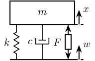
2.1 One mass
\begin{tikzpicture}
  % ====================
  % Parameters
  % ====================
  \def\massw{2.2}  % Width of the masses
  \def\massh{0.8}  % Height of the masses
  \def\spaceh{1.2} % Height of the springs/dampers
  \def\dispw{0.3}  % Width of the dashed line for the displacement
  \def\disph{0.5}  % Height of the arrow for the displacements
  \def\bracs{0.05} % Brace spacing vertically
  \def\brach{-10pt} % Brace shift horizontaly
  % ====================


  % ====================
  % Ground
  % ====================
  \draw (-0.5*\massw, 0) -- (0.5*\massw, 0);
  \draw[dashed] (0.5*\massw, 0) -- ++(\dispw, 0);
  \draw[->] (0.5*\massw+0.5*\dispw, 0) -- ++(0, \disph) node[right]{$w$};
  % ====================

  \begin{scope}[shift={(0, 0)}]
    % Mass
    \draw[fill=white] (-0.5*\massw, \spaceh) rectangle (0.5*\massw, \spaceh+\massh) node[pos=0.5]{$m$};

    % Spring, Damper, and Actuator
    \draw[spring] (-0.4*\massw, 0) -- (-0.4*\massw, \spaceh) node[midway, left=0.1]{$k$};
    \draw[damper] (0, 0)           -- ( 0, \spaceh)          node[midway, left=0.2]{$c$};
    \draw[actuator] ( 0.4*\massw, 0) -- (   0.4*\massw, \spaceh) node[midway, left=0.1](F){$F$};

    % Displacements
    \draw[dashed] (0.5*\massw, \spaceh) -- ++(\dispw, 0);
    \draw[->] (0.5*\massw+0.5*\dispw, \spaceh) -- ++(0, \disph) node[right]{$x$};

    % Legend
    % \draw[decorate, decoration={brace, amplitude=8pt}, xshift=\brach] %
    %   (-0.5*\massw, \bracs) -- (-0.5*\massw, \spaceh+\massh-\bracs) %
    %   node[midway,rotate=90,anchor=south,yshift=10pt]{};
  \end{scope}
\end{tikzpicture}
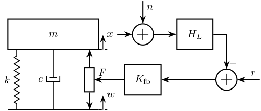
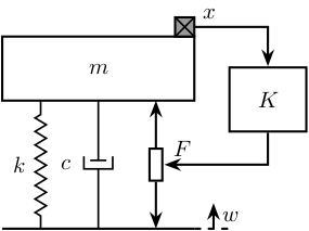
2.2 One mass - Control
\begin{tikzpicture}
  % ====================
  % Parameters
  % ====================
  \def\massw{3}  % Width of the masses
  \def\massh{1}  % Height of the masses
  \def\spaceh{2} % Height of the springs/dampers
  \def\dispw{0.3}  % Width of the dashed line for the displacement
  \def\disph{0.5}  % Height of the arrow for the displacements
  \def\bracs{0.05} % Brace spacing vertically
  \def\brach{-10pt} % Brace shift horizontaly
  % ====================


  % ====================
  % Ground
  % ====================
  \draw (-0.5*\massw, 0) -- (0.5*\massw, 0);
  \draw[dashed] (0.5*\massw, 0) -- ++(\dispw, 0);
  \draw[->] (0.5*\massw+0.5*\dispw, 0) -- ++(0, \disph) node[right]{$w$};
  % ====================

  \begin{scope}[shift={(0, 0)}]
    % Mass
    \draw[fill=white] (-0.5*\massw, \spaceh) rectangle (0.5*\massw, \spaceh+\massh) node[pos=0.5]{$m$};

    % Spring, Damper, and Actuator
    \draw[spring] (-0.4*\massw, 0) -- (-0.4*\massw, \spaceh) node[midway, left=0.1]{$k$};
    \draw[damper] (0, 0)           -- ( 0, \spaceh)          node[midway, left=0.2]{$c$};
    \draw[actuator={0.8}{0.3}] ( 0.4*\massw, 0) -- (    0.4*\massw, \spaceh) coordinate[midway, right=0.15](F);

    % Displacements
    \draw[dashed] (0.5*\massw, \spaceh) -- ++(\dispw, 0);
    \draw[->] (0.5*\massw+0.5*\dispw, \spaceh) -- ++(0, \disph) node[right](x){$x$};
  \end{scope}

  \node[block, right=1 of F] (Kfb) {$K_{\text{fb}}$};
  \node[addb={+}{}{-}{}{}, right=1.8 of Kfb] (add) {};
  \node[addb] (addn) at (x-|Kfb) {};
  \node[block, right=0.75 of addn] (Hl) {$H_L$};

  \draw[->] (x) -- (addn.west);
  \draw[->] (addn.east) -- (Hl.west);
  \draw[->] (Hl.east) -| (add.north);
  \draw[->] (add.west) -- (Kfb.east);
  \draw[->] (Kfb.west) -- (F) node[above right]{$F$};
  \draw[<-] (addn.north) -- ++(0,0.75) node[below right]{$n$};
  \draw[<-] (add.east) -- ++(0.75,0) node[above left]{$r$};
\end{tikzpicture}
2.3 Two masses
\begin{tikzpicture}
  % ====================
  % Parameters
  % ====================
  \def\massw{2.2}  % Width of the masses
  \def\massh{0.8}  % Height of the masses
  \def\spaceh{1.2} % Height of the springs/dampers
  \def\dispw{0.3}  % Width of the dashed line for the displacement
  \def\disph{0.5}  % Height of the arrow for the displacements
  \def\bracs{0.05} % Brace spacing vertically
  \def\brach{-10pt} % Brace shift horizontaly
  % ====================


  % ====================
  % Ground
  % ====================
  \draw (-0.5*\massw, 0) -- (0.5*\massw, 0);
  \draw[dashed] (0.5*\massw, 0) -- ++(\dispw, 0);
  \draw[->] (0.5*\massw+0.5*\dispw, 0) -- ++(0, \disph) node[right]{$x_{w}$};
  % ====================

  \begin{scope}[shift={(0, 0)}]
    % Mass
    \draw[fill=white] (-0.5*\massw, \spaceh) rectangle (0.5*\massw, \spaceh+\massh) node[pos=0.5]{$m_{g}$};

    % Spring, Damper, and Actuator
    \draw[spring] (-0.4*\massw, 0) -- (-0.4*\massw, \spaceh) node[midway, left=0.1]{$k_{g}$};
    \draw[damper] (0, 0)           -- ( 0, \spaceh)          node[midway, left=0.2]{$c_{g}$};
    \draw[actuator] ( 0.4*\massw, 0) -- (   0.4*\massw, \spaceh) node[midway, left=0.1](F){$F_{g}$};

    % Displacements
    \draw[dashed] (0.5*\massw, \spaceh) -- ++(\dispw, 0);
    \draw[->] (0.5*\massw+0.5*\dispw, \spaceh) -- ++(0, \disph) node[right]{$x_{g}$};

    % Legend
    % \draw[decorate, decoration={brace, amplitude=8pt}, xshift=\brach] %
    %   (-0.5*\massw, \bracs) -- (-0.5*\massw, \spaceh+\massh-\bracs) %
    %   node[midway,rotate=90,anchor=south,yshift=10pt]{};
  \end{scope}

  \begin{scope}[shift={(0, \spaceh+\massh)}]
    % Mass
    \draw[fill=white] (-0.5*\massw, \spaceh) rectangle (0.5*\massw, \spaceh+\massh) node[pos=0.5]{$m_{s}$};

    % Spring, Damper, and Actuator
    \draw[spring] (-0.4*\massw, 0) -- (-0.4*\massw, \spaceh) node[midway, left=0.1]{$k_{s}$};
    \draw[damper] (0, 0)           -- ( 0, \spaceh)          node[midway, left=0.2]{$c_{s}$};

    % Displacements
    \draw[dashed] (0.5*\massw, \spaceh) -- ++(\dispw, 0);
    \draw[->] (0.5*\massw+0.5*\dispw, \spaceh) -- ++(0, \disph) node[right]{$x_{s}$};

    % Legend
    % \draw[decorate, decoration={brace, amplitude=8pt}, xshift=\brach] %
    %   (-0.5*\massw, \bracs) -- (-0.5*\massw, \spaceh+\massh-\bracs) %
    %   node[midway,rotate=90,anchor=south,yshift=10pt]{};
  \end{scope}
\end{tikzpicture}

2.4 Three masses
\begin{tikzpicture}
  % ====================
  % Parameters
  % ====================
  \def\massw{2.2}  % Width of the masses
  \def\massh{0.8}  % Height of the masses
  \def\spaceh{1.2} % Height of the springs/dampers
  \def\dispw{0.3}  % Width of the dashed line for the displacement
  \def\disph{0.5}  % Height of the arrow for the displacements
  \def\bracs{0.05} % Brace spacing vertically
  \def\brach{-10pt} % Brace shift horizontaly
  % ====================


  % ====================
  % Ground
  % ====================
  \draw (-0.5*\massw, 0) -- (0.5*\massw, 0);
  \draw[dashed] (0.5*\massw, 0) -- ++(\dispw, 0);
  \draw[->] (0.5*\massw+0.5*\dispw, 0) -- ++(0, \disph) node[right]{$x_{w}$};
  % ====================

  % Granite
  \begin{scope}[shift={(0, 0)}]
    % Mass
    \draw[fill=white] (-0.5*\massw, \spaceh) rectangle (0.5*\massw, \spaceh+\massh) node[pos=0.5]{$m_{g}$};

    % Spring, Damper, and Actuator
    \draw[spring] (-0.4*\massw, 0) -- (-0.4*\massw, \spaceh) node[midway, left=0.1]{$k_{g}$};
    \draw[damper] (0, 0)           -- ( 0, \spaceh)          node[midway, left=0.2]{$c_{g}$};
    \draw[actuator] ( 0.4*\massw, 0) -- (   0.4*\massw, \spaceh) node[midway, left=0.1](F){$F_{g}$};

    % Displacements
    \draw[dashed] (0.5*\massw, \spaceh) -- ++(\dispw, 0);
    \draw[->] (0.5*\massw+0.5*\dispw, \spaceh) -- ++(0, \disph) node[right]{$x_{g}$};

    % Legend
    % \draw[decorate, decoration={brace, amplitude=8pt}, xshift=\brach] %
    %   (-0.5*\massw, \bracs) -- (-0.5*\massw, \spaceh+\massh-\bracs) %
    %   node[midway,rotate=90,anchor=south,yshift=10pt]{Support};
  \end{scope}

  % Stages
  \begin{scope}[shift={(0, \spaceh+\massh)}]
    % Mass
    \draw[fill=white] (-0.5*\massw, \spaceh) rectangle (0.5*\massw, \spaceh+\massh) node[pos=0.5]{$m_{s}$};

    % Spring, Damper, and Actuator
    \draw[spring] (-0.4*\massw, 0) -- (-0.4*\massw, \spaceh) node[midway, left=0.1]{$k_{s}$};
    \draw[damper] (0, 0)           -- ( 0, \spaceh)          node[midway, left=0.2]{$c_{s}$};

    % Displacements
    \draw[dashed] (0.5*\massw, \spaceh) -- ++(\dispw, 0);
    \draw[->] (0.5*\massw+0.5*\dispw, \spaceh) -- ++(0, \disph) node[right]{$x_{s}$};

    % Legend
    % \draw[decorate, decoration={brace, amplitude=8pt}, xshift=\brach] %
    %   (-0.5*\massw, \bracs) -- (-0.5*\massw, \spaceh+\massh-\bracs) %
    %   node[midway,rotate=90,anchor=south,yshift=10pt]{Actuator};
  \end{scope}

  % Hexapod
  \begin{scope}[shift={(0, 2*(\spaceh+\massh))}]
    % Mass
    \draw[fill=white] (-0.5*\massw, \spaceh) rectangle (0.5*\massw, \spaceh+\massh) node[pos=0.5]{$m_{v}$};

    % Spring, Damper, and Actuator
    \draw[spring] (-0.4*\massw, 0) -- (-0.4*\massw, \spaceh) node[midway, left=0.1]{$k_{v}$};
    \draw[damper] (0, 0)           -- ( 0, \spaceh)          node[midway, left=0.2]{$c_{v}$};

    % Displacements
    \draw[dashed] (0.5*\massw, \spaceh) -- ++(\dispw, 0);
    \draw[->] (0.5*\massw+0.5*\dispw, \spaceh) -- ++(0, \disph) node[right]{$x_{v}$};

    % Legend
    % \draw[decorate, decoration={brace, amplitude=8pt}, xshift=\brach] %
    %   (-0.5*\massw, \bracs) -- (-0.5*\massw, \spaceh+\massh-\bracs) %
    %   node[midway,rotate=90,anchor=south,yshift=10pt]{Flexibility};
  \end{scope}
\end{tikzpicture}

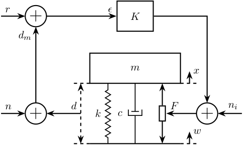
3 Control Based on distance measurement
\begin{tikzpicture}
  % Parameters
  \def\massw{3}
  \def\massh{1}
  \def\spaceh{2}

  % Ground
  \draw[] (-0.5*\massw, 0) -- (0.5*\massw, 0);
  % Mass
  \draw[] (-0.5*\massw, \spaceh) rectangle (0.5*\massw, \spaceh+\massh) node[pos=0.5](m){$m$};

  % Spring, Damper, and Actuator
  \draw[spring]   (-0.3*\massw, 0) -- (-0.3*\massw, \spaceh) node[midway, left=0.1]{$k$};
  \draw[damper]   ( 0, 0) -- ( 0, \spaceh) node[midway, left=0.3]{$c$};
  \draw[actuator] ( 0.3*\massw, 0) -- ( 0.3*\massw, \spaceh) node[midway](F){};

  % Displacements
  \draw[dashed] (0.5*\massw, 0) -- ++(0.2*\massw, 0);
  \draw[->] (0.6*\massw, 0) -- ++(0, 0.2*\spaceh) node[right]{$w$};
  \draw[dashed] (0.5*\massw, \spaceh) -- ++(0.2*\massw, 0);
  \draw[->] (0.6*\massw, \spaceh) -- ++(0, 0.2*\spaceh) node[right]{$x$};

  % Measurement
  \draw[dashed] (-0.5*\massw, 0) -- ++(-0.2*\massw, 0);
  \draw[dashed] (-0.5*\massw, \spaceh) -- ++(-0.2*\massw, 0);
  \draw[dashed, <->] (-0.6*\massw, 0) -- ++(0, \spaceh) node[midway](meas){};

  % Noise
  \node[addb, left=1 of meas] (addn) {};
  \draw[->] (meas.center) node[above left]{$d$} -- (addn.east);
  \draw[<-] (addn.west) -- ++(-0.8, 0) node[above right]{$n$};

  % Controller
  \node[block, above=1 of m] (K) {$K$};

  % Reference signal
  \node[addb] (addr) at (addn|-K){};
  \draw[<-] (addr.west) -- ++(-0.8, 0) node[above right]{$r$};
  \draw[->] (addn.north) -- (addr.south) node[below left]{$d_m$};
  \draw[->] (addr.east) -- (K.west) node[above left]{$\epsilon$};

  % Force injected and input noise
  \node[addb, right=1 of F] (addF) {};
  \draw[->] (K.east) -| (addF.north);
  \draw[->] (addF.west) -- (F.east) node[above right]{$F$};
  \draw[<-] (addF.east) -- ++(0.8, 0) node[above left]{$n_i$};
\end{tikzpicture}
4 Inertial Control
\begin{tikzpicture}
  % Parameters
  \def\massw{3}
  \def\massh{1}
  \def\spaceh{2}

  % Ground
  \draw[] (-0.5*\massw, 0) -- (0.5*\massw, 0);
  % Mass
  \draw[fill=white] (-0.5*\massw, \spaceh) rectangle (0.5*\massw, \spaceh+\massh) node[pos=0.5](m){$m$};

  % Spring, Damper, and Actuator
  \draw[spring]   (-0.3*\massw, 0) -- (-0.3*\massw, \spaceh) node[midway, left=0.1]{$k$};
  \draw[damper]   ( 0, 0) -- ( 0, \spaceh) node[midway, left=0.3]{$c$};
  \draw[actuator] ( 0.3*\massw, 0) -- ( 0.3*\massw, \spaceh) node[midway](F){};

  % Displacements
  \draw[dashed] (0.5*\massw, 0) -- ++(0.2*\massw, 0);
  \draw[->] (0.6*\massw, 0) -- ++(0, 0.2*\spaceh) node[below right]{$w$};

  % Inertial Sensor
  \node[inertialsensor] (inertials) at (0.5*\massw, \spaceh+\massh){};

  \node[block, above right=0.5*\massh and 1 of F.east] (K){$K$};

  \draw[->] (inertials.east) node[above right]{$x$} -| (K.north);
  \draw[->] (K.south) |- (F.east) node[above right]{$F$};
\end{tikzpicture}
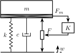
5 Force Feedback Control
\begin{tikzpicture}
  % Parameters
  \def\massw{3}
  \def\massh{1}
  \def\spaceh{2}

  % Ground
  \draw[] (-0.5*\massw, 0) -- (0.5*\massw, 0);
  % Mass
  \draw[fill=white] (-0.5*\massw, \spaceh) rectangle (0.5*\massw, \spaceh+\massh) node[pos=0.5](m){$m$};

  % Spring, Damper, and Actuator
  \draw[spring]   (-0.3*\massw, 0) -- (-0.3*\massw, \spaceh) node[midway, left=0.1]{$k$};
  \draw[damper]   ( 0, 0) -- ( 0, \spaceh) node[midway, left=0.3]{$c$};
  \draw[actuator] ( 0.3*\massw, 0) -- ( 0.3*\massw, \spaceh) node[midway](F){};

  % Force Sensor
  \node[forcesensor={\massw}{0.2}] (fsens) at (0, \spaceh){};

  % Displacements
  \draw[dashed] (0.5*\massw, 0) -- ++(0.2*\massw, 0);
  \draw[->] (0.6*\massw, 0) -- ++(0, 0.2*\spaceh) node[below right]{$w$};

  \node[block={0.7cm}{0.6cm}, above right=0.1*\massh and 1 of F.east] (K){$K$};

  \draw[->] (fsens.east) node[above right]{$F_m$} -| (K.north);
  \draw[->] (K.south) |- (F.east) node[above right]{$F$};
\end{tikzpicture}
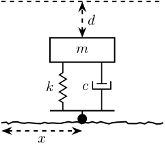
6 Inertial Sensor
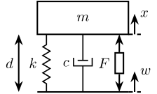
6.1 1dof geophone or accelerometer
\begin{tikzpicture}
  \def\massw{2.2}   % Width of the masses
  \def\massh{0.8}   % Height of the masses
  \def\spaceh{1.4}  % Height of the springs/dampers
  \def\dispw{0.3}   % Width of the dashed line for the displacement
  \def\disph{0.5}   % Height of the arrow for the displacements
  \def\bracs{0.05}  % Brace spacing vertically
  \def\brach{-10pt} % Brace shift horizontaly
  \draw (-0.5*\massw, 0) -- (0.5*\massw, 0);
  \draw[dashed] (0.5*\massw, 0) -- ++(\dispw, 0);
  \draw[->] (0.5*\massw+0.5*\dispw, 0) -- ++(0, \disph) node[right]{$w$};
  % Mass
  \draw[fill=white] (-0.5*\massw, \spaceh) rectangle (0.5*\massw, \spaceh+\massh) node[pos=0.5]{$m$};

  % Spring, Damper, and Actuator
  \draw[spring] (-0.4*\massw, 0) -- (-0.4*\massw, \spaceh) node[midway, left=0.1]{$k$};
  \draw[damper] (0, 0)           -- ( 0, \spaceh)          node[midway, left=0.2]{$c$};
  \draw[actuator] ( 0.4*\massw, 0) -- ( 0.4*\massw, \spaceh) node[midway, left=0.1](F){$F$};

  % Displacements
  \draw[dashed] (0.5*\massw, \spaceh) -- ++(\dispw, 0);
  \draw[->] (0.5*\massw+0.5*\dispw, \spaceh) -- ++(0, \disph) node[right]{$x$};

  \draw[<->] (-0.5*\massw+-1.5*\dispw, 0) -- node[midway, left]{$d$} ++(0, \spaceh);
\end{tikzpicture}
7 Mechanical Systems
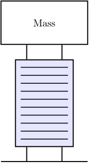
7.1 Piezoelectric Actuator
\begin{tikzpicture}
  \node[piezo={2}{3}{10}] (piezo) at (0, 0){};
  \node[draw, fill=white, anchor=south, minimum width=3cm, minimum height=1.5cm] (mass) at ($(piezo.north)+(0, 0.5)$) {Mass};
  \draw[] ($(piezo.south)+(-1.5, -0.5)$) -- ++(3, 0);
  \draw ($0.8*(piezo.north west)+0.2*(piezo.north east)$) -- ++(0, 0.5);
  \draw ($0.2*(piezo.north west)+0.8*(piezo.north east)$) -- ++(0, 0.5);
  \draw ($0.8*(piezo.south west)+0.2*(piezo.south east)$) -- ++(0, -0.5);
  \draw ($0.2*(piezo.south west)+0.8*(piezo.south east)$) -- ++(0, -0.5);
\end{tikzpicture}
8 3D
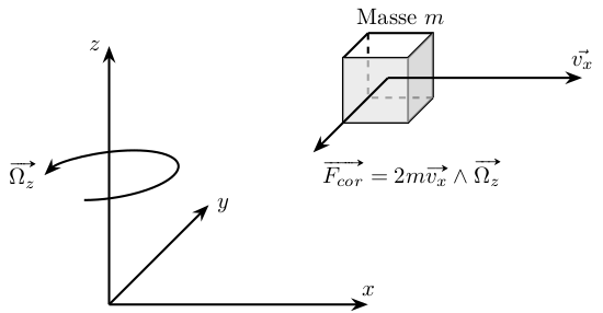
8.1 Coriolis Forces
\begin{tikzpicture}

  \draw[->] (0, 0, 0) -- (4, 0, 0) node[above] {$x$};
  \draw[->] (0, 0, 0) -- (0, 4, 0) node[left] {$z$};
  \draw[->] (0, 0, 0) -- (0, 0, -4) node[right] {$y$};

  \draw[->, style={canvas is zx plane at y=2}] (1, 0) arc (0:270:1) node[left]{$\vv{\Omega_z}$};


  \begin{scope}[shift={(4, 3.2, 0)}]
    \draw (1,0,0)--(1,1,0)--(0,1,0);
    \draw[dashed] (0,1,0)--(0,0,0)--(1,0,0);
    \draw (0,0,1)--(1,0,1)--(1,1,1)--(0,1,1)--(0,0,1);
    \draw[dashed] (0,0,0) -- (0,0,1);
    \draw (1,0,0) -- (1,0,1);
    \draw (1,1,0) -- (1,1,1);
    \draw (0,1,0) -- (0,1,1);

    \fill[fill=black!10, opacity=0.7] (0,0,1)--(1,0,1)--(1,1,1)--(0,1,1)--cycle;
    \fill[fill=black!20, opacity=0.7] (1,0,1)--(1,0,0)--(1,1,0)--(1,1,1)--cycle;

    \draw (0.5, 1, 0) node [above] {Masse $m$};

    \draw[->] (0.5, 0.5, 0.5) -- ++(3, 0, 0) node[above]{$\displaystyle\vec{v_x}$};

    \draw[->] (0.5, 0.5, 0.5) -- ++(0, 0, 3) node[below right]{$\displaystyle\vv{F_{cor}} = 2 m \vv{v_x} \wedge \vv{\Omega_z}$};
  \end{scope}

\end{tikzpicture}
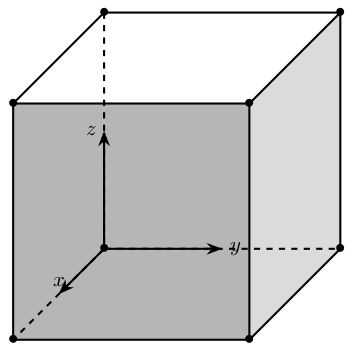
8.2 Cube
\begin{tikzpicture}
  \begin{scope}
    \fill[fill=black!40, opacity=0.7] (0,0,4) -- (4,0,4) -- (4,4,4) -- (0,4,4) -- cycle;
    \fill[fill=black!20, opacity=0.7] (4,0,4) -- (4,0,0) -- (4,4,0) -- (4,4,4) -- cycle;

    \draw (4,0,0)node{$\bullet$} -- (4,4,0)node{$\bullet$} -- (0,4,0)node{$\bullet$};
    \draw[dashed] (0,4,0) -- (0,0,0) -- (4,0,0);
    \draw (0,0,4)node{$\bullet$} -- (4,0,4)node{$\bullet$} -- (4,4,4)node{$\bullet$} -- (0,4,4)node{$\bullet$} -- (0,0,4);
    \draw[dashed] (0,0,0)node{$\bullet$} -- (0,0,4);
    \draw (4,0,0) -- (4,0,4);
    \draw (4,4,0) -- (4,4,4);
    \draw (0,4,0) -- (0,4,4);
  \end{scope}

  \draw[->] (0, 0, 0) -- (0, 0, 2) node[above] {$x$};
  \draw[->] (0, 0, 0) -- (2, 0, 0) node[right] {$y$};
  \draw[->] (0, 0, 0) -- (0, 2, 0) node[left]  {$z$};
\end{tikzpicture}
9 Gravity Compensation System
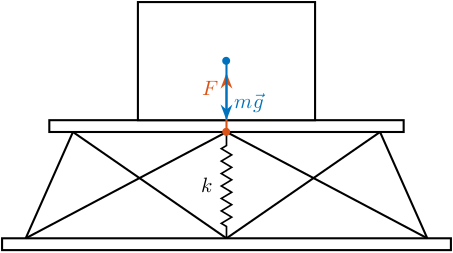
9.1 Null angle
\begin{tikzpicture}
  % Parameters definitions
  \def\baseh{0.2} % Height of the base
  \def\naceh{0.2} % Height of the nacelle
  \def\baser{3.8} % Radius of the base
  \def\nacer{3.0} % Radius of the nacelle

  \def\armr{0.2} % Radius of the arms
  \def\basearmborder{0.2}
  \def\nacearmborder{0.2}

  \def\xnace{0.0} % X position of the nacelle
  \def\ynace{2.0} % Y position of the nacelle
  \def\anace{0.0} % Angle of the nacelle

  \def\xbase{0.0} % X position of the base
  \def\ybase{0.0} % Y position of the base
  \def\abase{0.0} % Angle of the base

  % Hexapod1
  \begin{scope}[shift={(\xbase, \ybase)}, rotate=\abase]
    % Base
    \draw[fill=white] (-\baser, 0) rectangle (\baser, \baseh);
    \coordinate (armbasel) at (-\baser+\basearmborder+\armr, \baseh);
    \coordinate (armbasec) at (0, \baseh);
    \coordinate (armbaser) at (\baser-\basearmborder-\armr, \baseh);

    % Nacelle1
    \begin{scope}[shift={(\xnace, \ynace)}, rotate=\anace]
      \draw[fill=white] (-\nacer, 0) rectangle (\nacer, \naceh);
      \coordinate (armnacel) at (-\nacer+\nacearmborder+\armr, 0);
      \coordinate (armnacec) at (0, 0);
      \coordinate (armnacer) at (\nacer-\nacearmborder-\armr, 0);
    \end{scope}

    \draw (armbasec) -- (armnacer);
    \draw (armbasec) -- (armnacel);
    \draw (armbasel) -- (armnacel);
    \draw (armbasel) -- (armnacec);
    \draw (armbaser) -- (armnacec);
    \draw (armbaser) -- (armnacer);

    \draw[fill=white] (-0.5*\nacer, \ynace+\naceh) rectangle coordinate[pos=0.5](massc) (0.5*\nacer, \ynace+\naceh+2);
    \draw[spring] (0, \baseh) -- node[midway, left=0.1]{$k$} (0, \baseh+\ynace-\naceh) coordinate(stiffnessF);
    \draw[->, color=colorred] (stiffnessF)node{$\bullet$} -- ++(0, 1) node[below left]{$F$};
  \end{scope}
  \draw[->, color=colorblue] (massc)node{$\bullet$} -- ++(0, -1) node[above right]{$m\vec{g}$};
\end{tikzpicture}
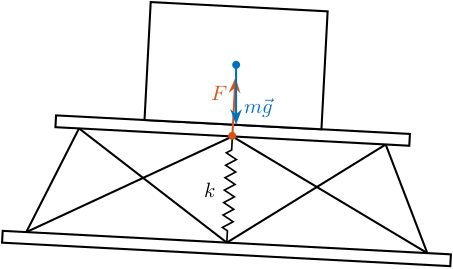
9.2 Maximum angle
\begin{tikzpicture}
  % Parameters definitions
  \def\baseh{0.2} % Height of the base
  \def\naceh{0.2} % Height of the nacelle
  \def\baser{3.8} % Radius of the base
  \def\nacer{3.0} % Radius of the nacelle

  \def\armr{0.2} % Radius of the arms
  \def\basearmborder{0.2}
  \def\nacearmborder{0.2}

  \def\xnace{0.0} % X position of the nacelle
  \def\ynace{2.0} % Y position of the nacelle
  \def\anace{0.0} % Angle of the nacelle

  \def\xbase{0.0} % X position of the base
  \def\ybase{0.0} % Y position of the base
  \def\abase{-3.0} % Angle of the base

  % Hexapod1
  \begin{scope}[shift={(\xbase, \ybase)}, rotate=\abase]
    % Base
    \draw[fill=white] (-\baser, 0) rectangle (\baser, \baseh);
    \coordinate (armbasel) at (-\baser+\basearmborder+\armr, \baseh);
    \coordinate (armbasec) at (0, \baseh);
    \coordinate (armbaser) at (\baser-\basearmborder-\armr, \baseh);

    % Nacelle1
    \begin{scope}[shift={(\xnace, \ynace)}, rotate=\anace]
      \draw[fill=white] (-\nacer, 0) rectangle (\nacer, \naceh);
      \coordinate (armnacel) at (-\nacer+\nacearmborder+\armr, 0);
      \coordinate (armnacec) at (0, 0);
      \coordinate (armnacer) at (\nacer-\nacearmborder-\armr, 0);
    \end{scope}

    \draw (armbasec) -- (armnacer);
    \draw (armbasec) -- (armnacel);
    \draw (armbasel) -- (armnacel);
    \draw (armbasel) -- (armnacec);
    \draw (armbaser) -- (armnacec);
    \draw (armbaser) -- (armnacer);

    \draw[fill=white] (-0.5*\nacer, \ynace+\naceh) rectangle coordinate[pos=0.5](massc) (0.5*\nacer, \ynace+\naceh+2);
    \draw[spring] (0, \baseh) -- node[midway, left=0.1]{$k$} (0, \baseh+\ynace-\naceh) coordinate(stiffnessF);
    \draw[->, color=colorred] (stiffnessF)node{$\bullet$} -- ++(0, 1) node[below left]{$F$};
  \end{scope}
  \draw[->, color=colorblue] (massc)node{$\bullet$} -- ++(0, -1) node[above right]{$m\vec{g}$};
\end{tikzpicture}
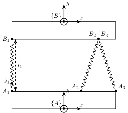
10 3Dof System
\begin{tikzpicture}
  \draw[fill=white] (-3, 0) -- (-3, 1) -- (3, 1) -- (3, 0) -- cycle;
  \draw[fill=white] (-3, 4) -- (-3, 5) -- (3, 5) -- (3, 4) -- cycle;

  \coordinate[] (a1) at (-3, 1);
  \coordinate[] (a2) at ( 1, 1);
  \coordinate[] (a3) at ( 3, 1);
  \coordinate[] (b1) at (-3, 4);
  \coordinate[] (b2) at ( 2, 4);
  \coordinate[] (b3) at ( 2, 4);

  \draw[spring] (a1) -- (b1);
  \draw[spring] (a2) -- (b2);
  \draw[spring] (a3) -- (b3);

  \node[] at (a1){$\bullet$}; \node[left]        at (a1) {$A_1$};
  \node[] at (a2){$\bullet$}; \node[above left]  at (a2) {$A_2$};
  \node[] at (a3){$\bullet$}; \node[above right] at (a3) {$A_3$};
  \node[] at (b1){$\bullet$}; \node[left]        at (b1) {$B_1$};
  \node[] at (b2){$\bullet$}; \node[above left]  at (b2) {$B_2$};
  \node[] at (b3){$\bullet$}; \node[above right] at (b3) {$B_3$};

  \draw[<->, dashed] ($(a1)+(0.2,0)$) -- node[midway, right]{$l_1$} ($(b1)+(0.2,0)$);
  \draw[->] (a1) -- ($0.8*(a1)+0.2*(b1)$) node[left]{$\hat{s}_1$};

  \begin{scope}[shift={(0,0)}]
    \draw[->] (0, 0) -- ++(1, 0) node[above]{$x$};
    \draw[->] (0, 0) -- ++(0, 1) node[right]{$y$};
    \draw[] (0, 0)node[]{$\bullet$} circle [radius=0.2] node[above left]{$\{A\}$};
  \end{scope}

  \begin{scope}[shift={(0,5)}]
    \draw[->] (0, 0) -- ++(1, 0) node[above]{$x$};
    \draw[->] (0, 0) -- ++(0, 1) node[right]{$y$};
    \draw[] (0, 0)node[]{$\bullet$} circle [radius=0.2] node[above left]{$\{B\}$};
  \end{scope}
\end{tikzpicture}
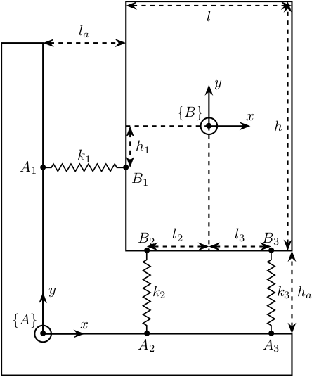
11 3Dof System - bis
\begin{tikzpicture}
  \draw[fill=white] (-1, -1) -- (-1, 7) -- (0, 7) -- (0, 0) -- (6, 0) -- (6, -1) -- cycle;

  \draw[->] (0, 0) -- ++(1, 0) node[above]{$x$};
  \draw[->] (0, 0) -- ++(0, 1) node[right]{$y$};
  \draw[] (0, 0)node[]{$\bullet$} circle [radius=0.2] node[above left]{$\{A\}$};

  \begin{scope}[shift={(4,5)}]
    \draw[fill=white] (-2, -3) rectangle (2, 3);

    \draw[->] (0, 0) -- ++(1, 0) node[above]{$x$};
    \draw[->] (0, 0) -- ++(0, 1) node[right]{$y$};
    \draw[] (0, 0)node[]{$\bullet$} circle [radius=0.2] node[above left]{$\{B\}$};

    \coordinate[] (b1) at (-2, -1);
    \coordinate[] (b2) at (-1.5, -3);
    \coordinate[] (b3) at ( 1.5, -3);

    \draw[dashed] (0, 0) -- ++(-2, 0);
    \draw[dashed] (0, 0) -- ++(0, -3);
    \draw[dashed, <->] (-1.9, 0) -- node[midway,right]{$h_1$} ++(0, -1);
    \draw[dashed, <->] (0, -2.9) -- node[midway,above]{$l_2$} ++(-1.5, 0);
    \draw[dashed, <->] (0, -2.9) -- node[midway,above]{$l_3$} ++( 1.5, 0);

    \draw[dashed, <->] (-2, 2.9) -- node[midway,below]{$l$} (2, 2.9);
    \draw[dashed, <->] ( 1.9, -3) -- node[midway,left]{$h$} (1.9, 3);
  \end{scope}

  \coordinate[] (a1) at (0, 4);
  \coordinate[] (a2) at (2.5, 0);
  \coordinate[] (a3) at (5.5, 0);

  \draw[spring] (a1) -- node[midway, above]{$k_1$} (b1);
  \draw[spring] (a2) -- node[midway, right]{$k_2$} (b2);
  \draw[spring] (a3) -- node[midway, right]{$k_3$} (b3);

  \node[] at (a1){$\bullet$}; \node[left]  at (a1) {$A_1$};
  \node[] at (a2){$\bullet$}; \node[below] at (a2) {$A_2$};
  \node[] at (a3){$\bullet$}; \node[below] at (a3) {$A_3$};
  \node[] at (b1){$\bullet$}; \node[below right] at (b1) {$B_1$};
  \node[] at (b2){$\bullet$}; \node[above] at (b2) {$B_2$};
  \node[] at (b3){$\bullet$}; \node[above] at (b3) {$B_3$};


  \draw[<->, dashed] (0, 7) -- node[midway, above]{$l_a$} ++(2, 0);
  \draw[<->, dashed] (6, 0) -- node[midway, right]{$h_a$} ++(0, 2);
  % \draw[->] (a1) -- ($0.8*(a1)+0.2*(b1)$) node[left]{$\hat{s}_1$};
\end{tikzpicture}
12 Rotating System
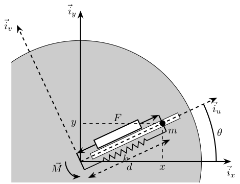
12.1 Rotating Frame - 1DoF
\begin{tikzpicture}
  % ================
  % Parameters
  % ================
  % Sizes
  \def\lengthi{5} % Size of unit vectors
  \def\lengthd{3} % Length of d
  \def\rotsize{4} % Size of the rotational stage
  \def\thetasize{4.5} % Size of the theta indicator
  \def\stagesize{0.3} % Size of the place for actuator and spring
  % Angles
  \def\thetau{25} % Current angle Theta
  \def\thetav{\thetau+90} % Current angle Theta+90
  % ================


  % Rotational Stage
  \draw[] (-10:\rotsize) arc (-10:125:\rotsize);
  \path[fill=black!20!white] (-10:\rotsize) arc (-10:125:\rotsize) |- cycle;
  % % Guidance
  % \draw[dashed, thin] (\thetau+1:\rotsize) -- ++(\thetau:-0.8*\rotsize);
  % \draw[dashed, thin] (\thetau-1:\rotsize) -- ++(\thetau:-0.8*\rotsize);


  % Inertial Frame
  \draw[->] (0, 0) -- (\lengthi, 0) node[below]{$\vec{i}_x$};
  \draw[->] (0, 0) -- (0, \lengthi) node[left]{$\vec{i}_y$};

  % Angle of rotation
  \draw[] (\thetasize, 0) arc (0:\thetau:\thetasize) node[midway, right]{$\theta$};

  % Rotating Scope
  \begin{scope}[rotate=\thetau]
    % Guidance
    \draw[fill=white, thin] (0.1*\rotsize,-0.1) rectangle (0.9*\rotsize, 0.1);

    % Rotating Frame
    \draw[->, dashed] (0, 0) -- (\lengthi, 0) node[below]{$\vec{i}_u$};
    \draw[->, dashed] (0, 0) -- (0, \lengthi) node[left]{$\vec{i}_v$};

    % Mass
    \coordinate[] (mass) at (\lengthd, 0);
    \draw[fill=black] (mass) circle (0.08);
    \node[below right=0.05 and 0.05 of mass] {$m$};

    % Spring and Actuator
    \draw[] (0, \stagesize) coordinate(act_start) -- (0, -\stagesize) coordinate(spring_start);
    \begin{scope}[shift={(mass)}]
    \draw[] (0, \stagesize) coordinate(act_end) -- (0, -\stagesize) coordinate(spring_end);
    \end{scope}

    \draw[actuator={1.6}{0.3}] (act_start) -- node[above=0.3]{$F$} (act_end);
    \draw[spring=0.7] (spring_start) -- node[below]{$k$} (spring_end);

    % Coordinates
    \draw[<->, dashed] (0, -2*\stagesize) coordinate(act_start) -- node[below]{$d$} (\lengthd, -2*\stagesize);
  \end{scope}

  % x-y position
  \coordinate[] (origin) at (0, 0);
  \draw[dashed, thin] (mass) -- (mass |- origin) node[below]{$x$};
  \draw[dashed, thin] (mass) -- (mass -| origin) node[left]{$y$};

  % Torque
  \draw[->] (-0.5, 0) arc (180:270:0.5) node[near start, left]{$\vec{M}$};
\end{tikzpicture}
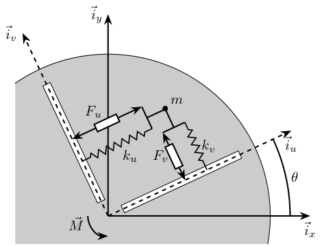
12.2 Rotating Frame - 2DoF
\begin{tikzpicture}
  % ================
  % Parameters
  % ================
  % Sizes
  \def\lengthi{5} % Size of unit vectors
  \def\lengthd{3} % Length of d
  \def\rotsize{4} % Size of the rotational stage
  \def\thetasize{4.5} % Size of the theta indicator
  \def\stagesize{0.3} % Size of the place for actuator and spring
  % Angles
  \def\thetau{25} % Current angle Theta
  \def\thetav{\thetau+90} % Current angle Theta+90
  % ================


  % Rotational Stage
  \draw[] (-10:\rotsize) arc (-10:125:\rotsize);
  \path[fill=black!20!white] (-10:\rotsize) arc (-10:125:\rotsize) |- cycle;

  % Inertial Frame
  \draw[->] (0, 0) -- (\lengthi, 0) node[below]{$\vec{i}_x$};
  \draw[->] (0, 0) -- (0, \lengthi) node[left]{$\vec{i}_y$};

  % Angle of rotation
  \draw[] (\thetasize, 0) arc (0:\thetau:\thetasize) node[midway, right]{$\theta$};
below
  % Rotating Scope
  \begin{scope}[rotate=\thetau]
    % Guidance
    \draw[fill=white, thin] (0.1*\rotsize, -0.1) rectangle (0.9*\rotsize, 0.1);
    \draw[fill=white, thin] (-0.1, 0.1*\rotsize) rectangle (0.1, 0.9*\rotsize);

    % Rotating Frame
    \draw[->, dashed] (0, 0) -- (\lengthi, 0) node[below]{$\vec{i}_u$};
    \draw[->, dashed] (0, 0) -- (0, \lengthi) node[left]{$\vec{i}_v$};

    % Mass
    \coordinate[] (mass) at (0.8*\lengthd, 0.6*\lengthd);
    \node[] at (mass){$\bullet$};
    \node[above right=0 and 0 of mass] {$m$};
    \draw[] (mass) -- ($(mass)+( 0, -0.5)$);
    \draw[] (mass) -- ($(mass)+(-0.5, 0)$);
    \draw[] ($(mass)+(-0.3, -0.5)$)coordinate(actv) -- ($(mass)+( 0.3, -0.5)$)coordinate(stiffv);
    \draw[] ($(mass)+(-0.5,  0.3)$)coordinate(actu) -- ($(mass)+(-0.5, -0.3)$)coordinate(stiffu);
    % \node[draw, minimum width=1cm, minimum height=1cm, transform shape] (massb) at (mass){};

    % Spring and Actuator for U
    \draw[actuator={0.6}{0.2}] (actu) -- node[above left]{$F_u$} (actu-|0,0);
    \draw[spring=0.2] (stiffu) -- node[below right]{$k_u$} (stiffu-|0,0);
    % Spring and Actuator for V
    \draw[actuator={0.6}{0.2}] (actv) -- node[left]{$F_v$} (actv|-0,0);
    \draw[spring=0.2] (stiffv) -- node[right]{$k_v$} (stiffv|-0,0);
  \end{scope}

  % x-y position
  % \coordinate[] (origin) at (0, 0);
  % \draw[dashed, thin] (mass) -- (mass |- origin) node[below]{$x$};
  % \draw[dashed, thin] (mass) -- (mass -| origin) node[left]{$y$};

  % Torque
  \draw[->] (-0.5, 0) arc (180:270:0.5) node[near start, left]{$\vec{M}$};
\end{tikzpicture}
13 Guiding Errors
\begin{tikzpicture}
  \tikzset{%
    guidingpath/.style={%
      decorate,
      decoration={random steps,segment length=2.8pt,amplitude=0.8pt}
    }
  }
  \def\massw{1.6}   % Width of the masses
  \def\massh{0.6}   % Height of the masses
  \def\spaceh{1.2}  % Height of the springs/dampers

  \draw[guidingpath] (-2,0) -- (2,0);
  \draw[dashed] (-2, 3) -- (2, 3);

  \draw[fill=black] (0, 0.1) circle [radius=0.1];
  \draw[] (0, 0.2) -- ++(0, 0.1);

  \begin{scope}[shift={(0, 0.3)}]
    \draw[] (-0.5*\massw, 0) -- (0.5*\massw, 0);

    % Mass
    \draw[fill=white] (-0.5*\massw, \spaceh) rectangle (0.5*\massw, \spaceh+\massh) node[pos=0.5]{$m$};
    \coordinate[] (masstop) at (0, \spaceh+\massh);

    % Spring, Damper, and Actuator
    \draw[spring] (-0.3*\massw, 0) -- (-0.3*\massw, \spaceh) node[midway, left=0.1]{$k$};
    \draw[damper] ( 0.3*\massw, 0) -- ( 0.3*\massw, \spaceh) node[midway, left=0.2]{$c$};
  \end{scope}

  \draw[dashed, <->] (masstop) -- node[midway, right]{$d$} (0, 3);

  \draw[dashed, <->] (-2, -0.2) -- node[midway, below]{$x$} (0, -0.2);
\end{tikzpicture}
14 Vibration analysis procedure
\begin{tikzpicture}
  \node[block, inner sep = 8pt, align=center] (1) {Description\\of structure};
  \node[block, inner sep = 8pt, align=center, right=0.6 of 1] (2) {Vibration\\Modes};
  \node[block, inner sep = 8pt, align=center, right=0.6 of 2] (3) {Response\\Levels};

  \draw[<->] (1) -- (2);
  \draw[<->] (2) -- (3);

  \node[above] (labelt) at (1.north) {Spatial Model};
  \node[] at (2|-labelt) {Modal Model};
  \node[] at (3|-labelt) {Response Model};

  \node[align = center, font=\tiny, below] (labelb) at (1.south) {Mass, Damping\\Stiffness};
  \node[align = center, font=\tiny] at (2|-labelb) {Natural Frequencies\\Mode Shapes};
  \node[align = center, font=\tiny] at (3|-labelb) {Frequency Responses\\Impulse Responses};
\end{tikzpicture}

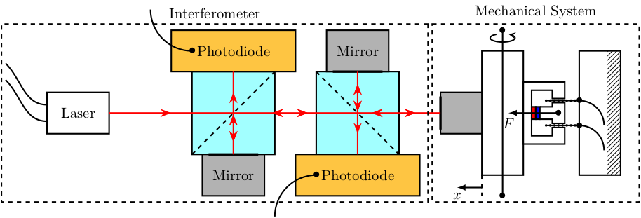
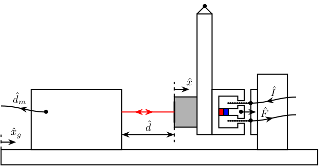
15 Pendulum Experiment
15.1 Side view
\begin{tikzpicture}
  % Colors
  \definecolor{mirror}{RGB}{178,178,178} % light grey

  % Pendulum
  \draw[fill=white] (0, 0) rectangle ++(0.5, 4);
  \coordinate[] (fixation) at (0.25, 4.25);
  \node[] at (fixation) {$\bullet$};
  \draw[] (fixation) -- (0.5, 4);
  \draw[] (fixation) -- (0, 4);

  % Voice Coil
  \begin{scope}[shift={(0.5, 0)}]
    \voicecoil{1.5}{1.5}{-90};
  \end{scope}

  % Corner Cube
  \draw[fill=mirror] (0, 0.25) rectangle (-0.75, 1.25);
  \draw[ultra thick] (-0.75, 0.4) -- (-0.75, 1.1);

  % Support
  \draw[fill=white] (-6.5, -1) rectangle (4, -0.5);

  % Interferometer
  \draw[fill=white] (-5.5, -0.5) rectangle ++(3, 2);

  % Voice coil fixation
  \draw[fill=white] (2, -0.5) rectangle ++(1, 2.5);

  % Coil Wires
  \draw[->-=.5] (vc_wire_one) node[]{$\bullet$} to[out=0,in=-180] ++(1.5, 0.2);
  \draw[-<-=.5] (vc_wire_two) node[]{$\bullet$} to[out=0,in=-180] node[midway, above]{$\hat{I}$} ++(1.5, 0.2);

  % LASER
  \draw[red, ->-=.6, -<-=.4] (-2.5, 0.75) -- (-0.75, 0.75);

  % F
  \draw[->] (vc_force) node[]{$\bullet$} -- ++(0.5, 0) node[right]{$\hat{F}$};

  % D
  \draw[<->] (-2.5, 0) -- node[midway, above]{$\hat{d}$} (-0.75, 0);
  \draw[dashed] (-0.75, 0.25) -- (-0.75, -0.25);

  % x
  \draw[->] (-0.75, 1.5) -- ++(0.5, 0) node[above]{$\hat{x}$};
  \draw[dashed] (-0.75, 1.25) -- (-0.75, 1.75);

  % Dm
  \coordinate[] (output_interferometer) at (-5, 0.75);
  \draw[->-=.6] (output_interferometer) node[]{$\bullet$} to[out=-180,in=0] node[pos=0.6, above]{$\hat{d}_m$} ++(-1.5, 0.2) ;

  % Xg
  \draw[->] (-6.5, -0.25) -- ++(0.5, 0) node[above]{$\hat{x}_g$};
  \draw[dashed] (-6.5, -0.5) -- ++(0, 0.5);

\end{tikzpicture}
15.2 Top view
\begin{tikzpicture}
  % Parameters definitions
  \def\splitw{2} % Width of the split mirrors
  \def\splith{2} % Height of the split mirrors

  \def\photow{1} % Width of the photodiodes
  \def\photoh{3} % Height of the photodiodes

  \def\mirrorw{1} % Width of the mirrors
  \def\mirrorh{1.5} % Height of the mirrors

  \def\pendulumw{3} % Width of the pendulum
  \def\pendulumh{1} % Height of the pendulum

  \def\pendmirrw{1} % Width of the mirror on the pendulum
  \def\pendmirrh{1} % Height of the mirror on the pendulum

  \def\firstinter{3} % First intersection of the beam
  \def\secinter{6}   % Second intersection of the beam
  \def\finalinter{9} % Intersection with the pendulum

  \def\magnetw{1.5} % Width of the magnet
  \def\magneth{1.0} % Height of the magnet

  \def\magnetwb{0.2} % Width of the borders of the magnet
  \def\magnethl{0.2} % Height of the low part of the magnet

  \def\magnetmw{0.3} % Width of the middle part of the magnet
  \def\magnetmh{0.2} % Height of the middle part of the magnet

  \def\magnethg{0.3} % Height of the gap of the magnet
  \def\magnetwg{0.7} % Width of the gap of the magnet

  % Colors
  \definecolor{split}{RGB}{162,255,255} % light blue
  \definecolor{photodiode}{RGB}{254,197,66} % light orange
  \definecolor{mirror}{RGB}{178,178,178} % light grey
  \begin{scope}[rotate=-90]
    % Label positions
    \pgfmathsetmacro{\labelright}{0.5*\splitw+\photow+0.5}%
    \pgfmathsetmacro{\labelleft}{-0.5*\splitw-\photow-0.5}%

    % Laser Source
    \begin{scope}[shift={(0, 0)}]
      \draw[fill=white] (-0.5, 0) rectangle node[pos=0.5]{Laser} (0.5, -1.5);
      \draw[] (-0.2, -1.5) to[out=-90,in=45] ++(-1, -1);
      \draw[] ( 0.2, -1.5) to[out=-90,in=45] ++(-1, -1);
    \end{scope}

    % Split Mirror 1
    \begin{scope}[shift={(0, \firstinter)}]
      \draw[fill=split] (-0.5*\splitw, -0.5*\splith) rectangle (0.5*\splitw, 0.5*\splith);
      \draw[dashed] (0.5*\splitw, -0.5*\splith) -- (-0.5*\splitw, 0.5*\splith);
    \end{scope}
    % Photodiode 1
    \begin{scope}[shift={(-0.5*\splitw, \firstinter)}]
      \draw[fill=photodiode] (-\photow, -0.5*\photoh) rectangle node[pos=0.5]{Photodiode} (0, 0.5*\photoh);
      \draw[] (-0.5*\photow, -0.5*\photoh+0.5*\photow) node[]{$\bullet$} to[out=-90,in=0] ++(-\photow, -\photow);
    \end{scope}
    % Mirror 1
    \begin{scope}[shift={(0.5*\splitw, \firstinter)}]
      \draw[fill=mirror] (0, -0.5*\mirrorh) rectangle node[pos=0.5]{Mirror} (\mirrorw, 0.5*\mirrorh);
      \draw[ultra thick] (0, -0.4*\mirrorh) -- (0, 0.4*\mirrorh);
    \end{scope}

    % Split Mirror 2
    \begin{scope}[shift={(0, \secinter)}]
      \draw[fill=split] (-0.5*\splitw, -0.5*\splith) rectangle (0.5*\splitw, 0.5*\splith);
      \draw[dashed] (-0.5*\splitw, -0.5*\splith) -- (0.5*\splitw, 0.5*\splith);
    \end{scope}
    % Photodiode 2
    \begin{scope}[shift={(0.5*\splitw, \secinter)}]
      \draw[fill=photodiode] (0, -0.5*\photoh) rectangle node[pos=0.5]{Photodiode} (\photow, 0.5*\photoh);
      \draw[] (0.5*\photow, -0.5*\photoh+0.5*\photow) node[]{$\bullet$} to[out=-90,in=-180] ++(\photow, -\photow);
    \end{scope}
    % Mirror 2
    \begin{scope}[shift={(-0.5*\splitw, \secinter)}]
      \draw[fill=mirror] (-\mirrorw, -0.5*\mirrorh) rectangle node[pos=0.5]{Mirror} (0, 0.5*\mirrorh);
      \draw[ultra thick] (0, -0.4*\mirrorh) -- (0, 0.4*\mirrorh);
    \end{scope}

    % Pendulum
    \begin{scope}[shift={(0, \finalinter)}]
      % Overall delimitation of the pendulum system
      \coordinate[] (delimmec) at (-0.5*\pendulumw-0.5*\magnetmw-0.5, -1.2);
      \coordinate[] (delimmecbis) at (0.5*\pendulumw+0.5*\magnetmw+0.5, \pendulumh+2.8);
      \draw[dashed] (delimmec) rectangle (delimmecbis);
      \path[] (-0.5*\pendulumw-0.5*\magnetmw-0.5, -1.2) -- (-0.5*\pendulumw-0.5*\magnetmw-0.5, \pendulumh+2.8) node[midway,above]{Mechanical System};

      \draw[fill=white] (-0.5*\pendulumw, 0) rectangle (0.5*\pendulumw, \pendulumh);
      \draw[] (-0.5*\pendulumw-0.5, 0.5*\pendulumh) node[]{$\bullet$} -- (0.5*\pendulumw+0.5, 0.5*\pendulumh) node[]{$\bullet$};
      \node[] at (-0.5*\pendulumw-0.3, 0.5*\pendulumh) {\AxisRotator[rotate=-90]};
      \draw[dashed] (0.5*\pendulumw, 0) -- ++(0.5, 0);
      \draw[->, >=latex] (0.5*\pendulumw+0.3, 0) -- ++(0, -0.6) node[below]{$x$};
      \draw[fill=mirror] (-0.5*\pendmirrw, -\pendmirrh) rectangle (0.5*\pendmirrw, 0);
      \draw[ultra thick] (-0.4*\pendmirrw, -\pendmirrh) -- (0.4*\pendmirrw, -\pendmirrh);
    \end{scope}

    % Magnet
    \begin{scope}[shift={(0, \finalinter+\pendulumh)}]
      \draw[fill=white] (0, 0) -| ++(0.5*\magnetw, \magneth) -| ++(-0.5*\magnetw+0.5*\magnetwg, -\magnethg) -| (0.5*\magnetw-\magnetwb, \magnethl) -| (-0.5*\magnetw+\magnetwb, \magneth-\magnethg) -| (-0.5*\magnetwg, \magneth) -| (-0.5*\magnetw, 0) -- (cycle);
      % Magnet
      \begin{scope}[shift={(0, \magnethl)}]
        \draw[fill=red]  (-0.5*\magnetmw, 0) rectangle (0.5*\magnetmw, 0.5*\magnetmh);
        \draw[fill=blue] (-0.5*\magnetmw, 0.5*\magnetmh) rectangle (0.5*\magnetmw, \magnetmh);
        % Top conductive Magnet
        \draw[fill=white] (-0.5*\magnetmw, \magnetmh) -| (0.5*\magnetmw, -\magnethl+\magneth-\magnethg) -| ++(0.1, \magnethg) -| ++(-0.2-\magnetmw, -\magnethg) -| (-0.5*\magnetmw, \magnetmh);
        % Force
        \draw[->, >=latex] (0, -0.8*\magnethl+0.8*\magneth)node[]{$\bullet$} -- ++(0, -1.2) node[below]{$F$};
      \end{scope}

      % Coil
      \pgfmathsetmacro{\coilwidth}{0.5*0.5*\magnetmw+0.5*0.1+0.25*\magnetwg}%
      \draw[] ( \coilwidth, \magneth-1.5*\magnethg) -- ++(0, 0.8);
      \draw[] (-\coilwidth, \magneth-1.5*\magnethg) -- ++(0, 0.8);
      % Point on the coil
      \foreach \x in {0,0.1,...,0.8}
      {\node[circle,inner sep=0.6pt,fill] at ( \coilwidth, \x+\magneth-1.5*\magnethg);
        \node[circle,inner sep=0.6pt,fill] at (-\coilwidth, \x+\magneth-1.5*\magnethg);}
      % Actuator Attachement
      \draw[fill=white] (-0.5*\pendulumw, \magneth-1.5*\magnethg+0.8) rectangle ++(\pendulumw, \pendulumh);
      % Ground
      \node (ground) [anchor=south, ground, minimum width={\pendulumw cm}, rotate=-90] at (0, \magneth-1.5*\magnethg+0.8+\pendulumh) {};

      % Coil Wires
      \draw[] ( \coilwidth, \magneth-1.5*\magnethg+0.8) node[]{$\bullet$} to[out=90,in=-180] ++(0.6*\pendulumh, 0.6*\pendulumh);
      \draw[] (-\coilwidth, \magneth-1.5*\magnethg+0.8) node[]{$\bullet$} to[out=90,in=-180] ++(0.6*\pendulumh, 0.6*\pendulumh);
    \end{scope}

    % LASER
    \draw[red, ->-=.5] (0, 0) -- (0, \firstinter);
    \draw[red, ->-=.6, -<-=.4] (0, \firstinter) -- (-, \secinter);
    \draw[red, ->-=.7, -<-=.3] (0, \secinter) -- (0, \finalinter-\pendmirrh);

    \draw[red, ->-=.7, -<-=.3] (0, \firstinter) -- ++( 0.5*\splitw, 0);
    \draw[red, ->-=.5] (0, \firstinter) -- ++(-0.5*\splitw, 0);
    \draw[red, ->-=.5] (0, \secinter)   -- ++( 0.5*\splitw, 0);
    \draw[red, ->-=.7, -<-=.3] (0, \secinter)   -- ++(-0.5*\splitw, 0);

    % Delimitation of the Interferometer system
    \coordinate[] (deliminter) at ($(delimmec)-(0, 0.1)$);
    \coordinate[] (deliminterbis) at ($(delimmecbis)-(0, 15.4)$);
    \draw[dashed] (deliminter) rectangle (deliminterbis);
    \path[] (deliminter) -- (deliminterbis -| deliminter) node[midway, above]{Interferometer};
  \end{scope}

\end{tikzpicture}